Upload presentasi
Presentasi sedang didownload. Silahkan tunggu

1
Media Transmisi & TEKNOLOGI TRANSMISI

2
Tipe-tipe Media Transmisi
Guided transmission media Kabel tembaga Open Wires Coaxial Twisted Pair Kabel serat optik Unguided transmission media infra merah gelombang radio microwave: terrestrial maupun satellite

3
Source: Stallings, Data & Computer Communications, Figure 4.1
ELF = Extremely low frequency VF = Voice frequency VLF = Very low frequency LF = Low frequency MF = Medium frequency HF = High frequency VHF = Very high frequency UHF = Ultra high frequency SHF = Super high frequency EHF = Extremely high frequency

4
Guided Transmission Media

5
Kabel Tembaga Paling lama dan sudah biasa digunakan
Kelemahan: redaman tinggi dan sensitif terhadap interferensi Redaman pada suatu kabel tembaga akan meningkat bila frekuensi dinaikkan Kecepatan rambat sinyal di dalam kabel tembaga mendekati km/detik Tiga jenis kabel tembaga yang biasa digunakan: Open wire Coaxial Twisted Pair

6
Open wire Sudah jarang digunakan Kelemahan:
Terpengaruh kondisi cuaca dan lingkungan Kapasitas terbatas (hanya sekitar 12 kanal voice)
")
7
RG58 coax and BNC Connector
Coaxial Bandwidth tinggi dan lebih kebal terhadap interferensi Contoh penggunaan : pada antena TV, LAN dsb. (D) (C) (B) (A) RG58 coax and BNC Connector
 (C) (B) (A) RG58 coax and BNC Connector.")
8
Twisted pair Kabel dipilin untuk mengeliminasi crosstalk
Menggunakan “balance signaling” untuk mengeliminasi pengaruh interferensi (noise)
")
10
Twist length kabel telepon: 5-15 cm
Twist length Cat-3 UTP : cm Twist length Cat-5 : 2-4 cm Pada suatu bundel twisted pair (lebih dari satu pasang), twist length masing-masing pasangan dibedakan untuk mencegah crosstalk antar pasangan
, twist length masing-masing pasangan dibedakan untuk mencegah crosstalk antar pasangan.")
11
Twisted Pair Connectors
Kabel twisted pair untuk komputer menggunakan konektor RJ45 (8 pin) Kabel twisted pair untuk telepon menggunakan konektor RJ11
 Kabel twisted pair untuk telepon menggunakan konektor RJ11.")
12
Serat Optik Kabel serat optik terdiri dari :
Silinder dalam berbahan gelas yang disebut inti atau core Silinder luar terbuat dari bahan gelas atau plastik yang disebut cladding atau pembungkus inti Bahan pelidung serat yang membungkus cladding

13
Mengapa cahaya bisa bergerak sepanjang serat optik?
Karena ada proses yang disebut Total Internal Reflection (TIR) TIR dimungkinkan dengan membedakan indeks bias (n) antara core dan clading Dalam hal ini ncore > ncladding Memanfaatkan hukum Snellius
 TIR dimungkinkan dengan membedakan indeks bias (n) antara core dan clading. Dalam hal ini ncore > ncladding. Memanfaatkan hukum Snellius.")
14
ncore > ncladding Pantulan terjadi Bila sudut jatuh
> sudut kritis ncore > ncladding Pembiasan

15
Dasar Optik (5) Sudut Kritis
Cahaya yang merambat jika jatuh pada media permukaan datar dan bening, tidak dibelokkan seluruhnya tetapi sebagian dipantulkan dan sebagaian dibiaskan. Hubungan antara bagian cahaya yang dipantulkan dan cahaya yang dibelookan bergantung pada indeks bias media dan sudut datang cahaya. Jika cahaya yang datang dari materi dengan bias kecil ke materi dengan indeks bias besar, maka cahaya tersebut akan selkalu dibiaskan. (melewati garis normal). Jika cahaya yangdatangdari materi dengan indeks bias besar ke materi dengan indeks kecil, maka akan dibiaskan menjauhi garis normal. Jika besar sudut datang cahaya (θ1) diperbesar sampai satu nilai tertentu maka seluruh cahaya akan dipantulkan secara total, besarnya sudut datang tersebut, disebut sudut kritis, hal ini merupakan kondisi ideal untuk mentransmisikan cahaya dalam serat optik Jika sudut datang (θ1) > sudut kritis (θe) maka cahaya akan dipantulkan seluruhnya ≈ 100 %
. Jika cahaya yangdatangdari materi dengan indeks bias besar ke materi dengan indeks kecil, maka akan dibiaskan menjauhi garis normal. Jika besar sudut datang cahaya (θ1) diperbesar sampai satu nilai tertentu maka seluruh cahaya akan dipantulkan secara total, besarnya sudut datang tersebut, disebut sudut kritis, hal ini merupakan kondisi ideal untuk mentransmisikan cahaya dalam serat optik. Jika sudut datang (θ1) > sudut kritis (θe) maka cahaya akan dipantulkan seluruhnya ≈ 100 %")
16
Apabila kabel serat optik dilengkungkan, dapat terjadi loss

17
θNA Cahaya yang dapat dimasukkan ke dalam serat optik harus disuntikkan pada sudut yang lebih kecil daripada θNA. Ini dipersyaratkan sebagai Numerical Apperture (NA)
")
18
Salah satu cara untuk mengidenifikasi konstruksi kabel optik adalah dengan menggunakan perbandingan antara diameter core dan cladding. Sebagai contoh adalah tipe kabel 62.5/125. Artinya diamater core 62,5 micron dan diameter cladding 125 micron Contoh lain tipe kabel:50/125, 62.5/125 dan 8.3/125 Jumlah core di dalam satu kabel bisa antara 4 s.d. 144

19
Klasifikasi Serat Optik
Berdasarkan mode gelombang cahaya yang berpropagasi pada serat optik Multimode Fibre Singlemode Fibre Berdasarkan perubahan indeks bias bahan Step index fibre Gradded index fibre

20
Step Index Fiber vs Gradded Index Fiber
Pada step index fiber, perbedaan antara index bias inti dengan index bias cladding sangat drastis

21
Contoh profile gradded index:
Pada gradded index fiber, perbedaan index bias bahan dari inti sampai cladding berlangsung secara gradual Contoh profile gradded index: Untuk 0 ≤r ≤ a r = jari-jari di dalam inti serat a = jari-jari maksimum inti serat

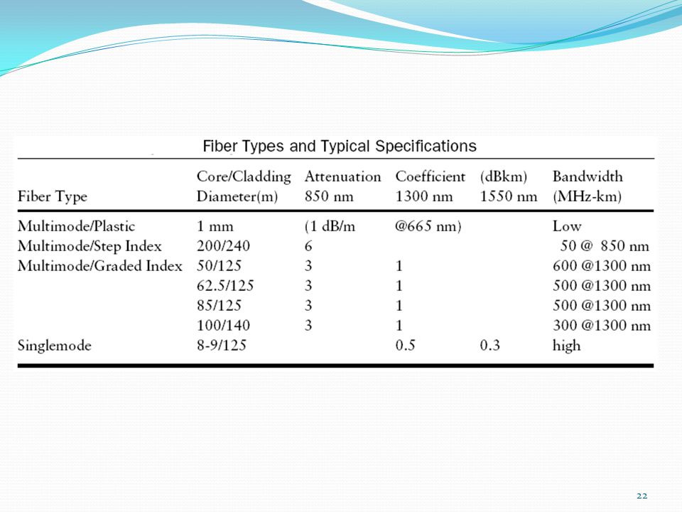
23
Jenis-jenis kabel serat optik
Step-index multimode. Used with 850nm, 1300 nm source. Graded-index multimode. Used with 850nm, 1300 nm source. Single mode. Used with 1300 nm, 1550 nm source.

24
Unguided Transmission Media

25
Microwave Range frekuensi: 1 - 40 GHz
Transmisi dilakukan secara line of sight (LOS) Tidak dapat menembus dinding (solid objects; contoh: bangunan) Digunakan untuk komunikasi terrestrial (earth-to-earth) dan satelit Di atas 8 GHz, diserap oleh partikel air Jadi hujan dapat menggagalkan transmisi
 Tidak dapat menembus dinding (solid objects; contoh: bangunan) Digunakan untuk komunikasi terrestrial (earth-to-earth) dan satelit. Di atas 8 GHz, diserap oleh partikel air. Jadi hujan dapat menggagalkan transmisi.")
26
Satellite Microwave Range frekuensi optimal yang digunakan adalah: GHz Dibawah 1 GHz akan terpengaruh dari alam dan man-made sources Di atas 10 GHz akan teredam atmosfir Geosynchronous satellites have an orbital radius of 35,784 km.

27
Satellite Systems Sistem orbit Low dan medium memiliki delay yang lebih rendah Menawarkan kecepatan 2Mbps Iridium originally planned to use 77 satellites (from whence the name -- Iridium is element 77) in circumpolar orbits. As of 2000, the system had been unprofitable for several years and in the absence of any buyers, Motorola proposed to destroy it by sending the satellites into delaying orbits and let them burn up. In May 2000, a potential buyer offered $100M for the entire system -- about 1% of the original cost. Operating costs are around $ M per month.
 in circumpolar orbits. As of 2000, the system had been unprofitable for several years and in the absence of any buyers, Motorola proposed to destroy it by sending the satellites into delaying orbits and let them burn up. In May 2000, a potential buyer offered $100M for the entire system -- about 1% of the original cost. Operating costs are around $ M per month.")
28
Terrestrial Wireless Digunakan untuk keperluan telekomunikasi komersial, telepon seluler, serta LAN jarak pendek dan menengah Contoh: wireless LAN IEEE yang bekerja pada band 2.4 The Advanced Mobile Phone System (AMPS) is an analog system developed in the U.S. It uses 30 kHz data channels but can pack 48.6 kbps into each. Channels are shared so that each user gets a data rate of only 13 kbps. GSM uses both FDM and TDM, divides the spectrum into 200 kHz bands, shared by multiple users. Encryption is used to prevent eavesdropping. Information on Lucent’s wireless products is at
 is an analog system developed in the U.S. It uses 30 kHz data channels but can pack 48.6 kbps into each. Channels are shared so that each user gets a data rate of only 13 kbps. GSM uses both FDM and TDM, divides the spectrum into 200 kHz bands, shared by multiple users. Encryption is used to prevent eavesdropping. Information on Lucent’s wireless products is at")
29
Propagasi Wireless Sinyal berjalan melalui tiga rute
Gelombang tanah (Ground wave) Mengikuti contour bumi Sd 2MHz Radio AM Gelombang langit (Sky wave) Amateur radio, BBC world service, Voice of America Sinyal dipantulkan dari lapisan ionosphere dari bagian atas atmosphere (Persisnya refracted) Line of sight Di atas 30Mhz Mungkin lebih dari optical line of sight krn refraction
 Mengikuti contour bumi. Sd 2MHz. Radio AM. Gelombang langit (Sky wave) Amateur radio, BBC world service, Voice of America. Sinyal dipantulkan dari lapisan ionosphere dari bagian atas atmosphere. (Persisnya refracted) Line of sight. Di atas 30Mhz. Mungkin lebih dari optical line of sight krn refraction.")
30
Modulasi & Multiplexing

31
Apa itu Modulasi ? Modulasi adalah pengaturan parameter dari sinyal pembawa (carrier) yang berfrequency tinggi sesuai sinyal informasi (pemodulasi) yang frequencynya lebih rendah, sehingga informasi tadi dapat disampaikan.
 yang berfrequency tinggi sesuai sinyal informasi (pemodulasi) yang frequencynya lebih rendah, sehingga informasi tadi dapat disampaikan.")
32
Mengapa Perlu Modulasi ?
Meminimalisasi interferensi sinyal pada pengiriman informasi yang menggunakan frequency sama atau berdekatan Dimensi antenna menjadi lebih mudah diwujudkan Sinyal termodulasi dapat dimultiplexing dan ditransmisikan via sebuah saluran transmisi

33
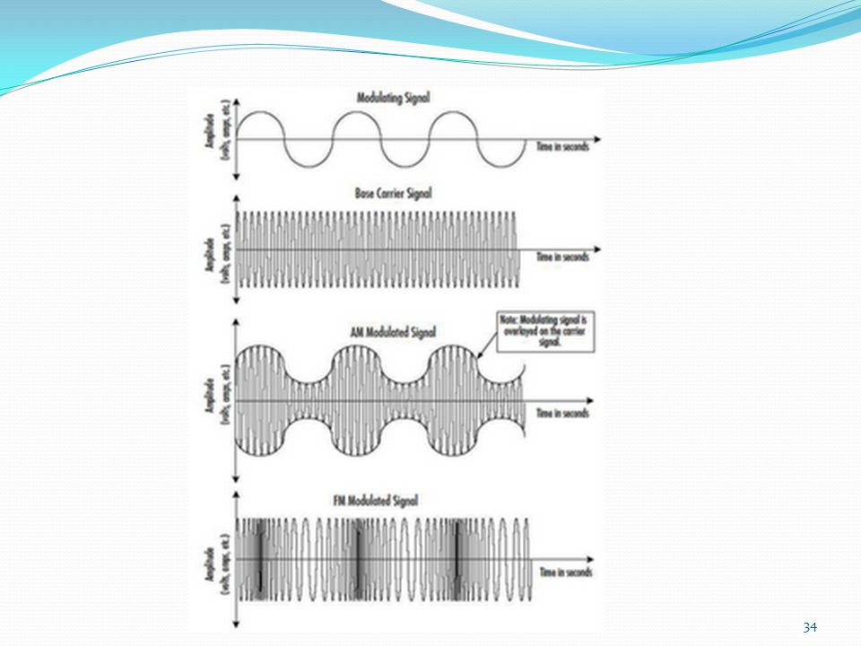
Jenis Modulasi Modulasi Analog
Modulasi Sinyal Continue (continues wave) : Amplitude Modulation (AM) Modulasi Sudut (Angle Modulation) : Phase Modulation (PM) Frequency Modulation (FM) Modulsi Pulsa Pulse Amplitude Modulation (PAM) Pulse Wide Modulation (PWM)
 : Amplitude Modulation (AM) Modulasi Sudut (Angle Modulation) : Phase Modulation (PM) Frequency Modulation (FM) Modulsi Pulsa. Pulse Amplitude Modulation (PAM) Pulse Wide Modulation (PWM)")
35
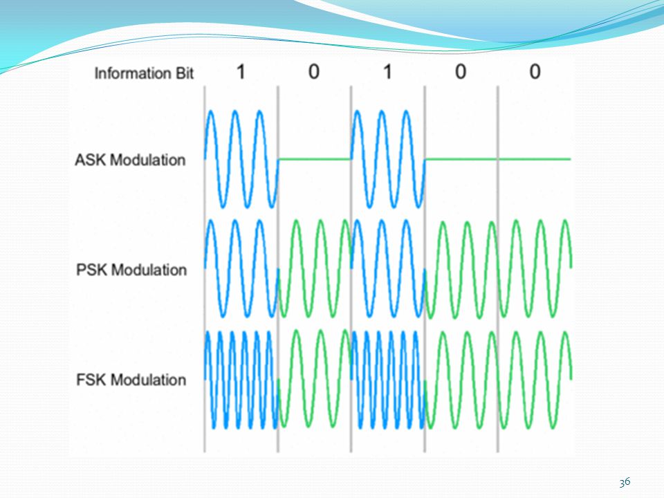
Modulasi Digital : Pulse Code Modulation (PCM) Delta Modulation (DM)
Amplitude Shift Keying (ASK) Frequency Shift Keying (FSK) Phase Shift Keying (PSK) Quadrature Amplitude Modulation (QAM) Quaternary PSK (QPSK) Continous Phase FSK (CPFSK) dll
 Frequency Shift Keying (FSK) Phase Shift Keying (PSK) Quadrature Amplitude Modulation (QAM) Quaternary PSK (QPSK) Continous Phase FSK (CPFSK) dll.")
37
Aplikasi modulasi di sekitar kita

38
Multiplexing To make efficient use of high-speed telecommunications lines, some form of multiplexing is used Multiplexing allows several transmission sources to share the same transmission media Trunks on long-haul networks are high-capacity fiber, coaxial, or microwave links Common forms of multiplexing are Frequency Division Multiplexing (FDM), Time Division Multiplexing (TDM), and Statistical TDM (STDM). To make efficient use of high-speed telecommunications lines, some form of multiplexing is used. Multiplexing allows several transmission sources to share a larger transmission capacity. A common application of multiplexing is in long-haul communications. Trunks on long-haul networks are high-capacity fiber, coaxial, or microwave links. These links can carry large numbers of voice and data transmissions simultaneously using multiplexing. Common forms of multiplexing are frequency division multiplexing (FDM), time division multiplexing (TDM), and statistical TDM (STDM). Stallings DCC8e Figure 8.1 depicts the multiplexing function in its simplest form. There are n inputs to a multiplexer. The multiplexer is connected by a single data link to a demultiplexer. The link is able to carry n separate channels of data. The multiplexer combines (multiplexes) data from the n input lines and transmits over a higher-capacity data link. The demultiplexer accepts the multiplexed data stream, separates (demultiplexes) the data according to channel, and delivers data to the appropriate output lines. 2/28
, Time Division Multiplexing (TDM), and Statistical TDM (STDM). To make efficient use of high-speed telecommunications lines, some form of multiplexing is used. Multiplexing allows several transmission sources to share a larger transmission capacity. A common application of multiplexing is in long-haul communications. Trunks on long-haul networks are high-capacity fiber, coaxial, or microwave links. These links can carry large numbers of voice and data transmissions simultaneously using multiplexing. Common forms of multiplexing are frequency division multiplexing (FDM), time division multiplexing (TDM), and statistical TDM (STDM). Stallings DCC8e Figure 8.1 depicts the multiplexing function in its simplest form. There are n inputs to a multiplexer. The multiplexer is connected by a single data link to a demultiplexer. The link is able to carry n separate channels of data. The multiplexer combines (multiplexes) data from the n input lines and transmits over a higher-capacity data link. The demultiplexer accepts the multiplexed data stream, separates (demultiplexes) the data according to channel, and delivers data to the appropriate output lines. 2/28.")
39
Multiplexing Techniques
Frequency Division Multiplexing (FDM) Each signal is allocated a different frequency band Usually used with analog signals Modulation equipment is needed to move each signal to the required frequency band (channel) Multiple carriers are used, each is called sub-carrier Multiplexing equipment is needed to combine the modulated signals Dime Division Multiplexing (TDM) Usually used with digital signals or analog signals carrying digital data Data from various sources are carried in repetitive frames Each frame consists of of a set of time slots Each source is assigned one or more time slots per frame Frequency division multiplexing can be used with analog signals. A number of signals are carried simultaneously on the same medium by allocating to each signal a different frequency band. FDM is possible when the useful bandwidth of the transmission medium exceeds the required bandwidth of signals to be transmitted. A number of signals can be carried simultaneously if each signal is modulated onto a different carrier frequency and the carrier frequencies are sufficiently separated that the bandwidths of the signals do not significantly overlap. A general case of FDM is shown in Stallings DCC8e Figure 8.2a. Six signal sources are fed into a multiplexer, which modulates each signal onto a different frequency (f1, …, f6). Each modulated signal requires a certain bandwidth centered on its carrier frequency, referred to as a channel. To prevent interference, the channels are separated by guard bands, which are unused portions of the spectrum. The composite signal transmitted across the medium is analog. Note, however, that the input signals may be either digital or analog. In the case of digital input, the input signals must be passed through modems to be converted to analog. In either case, each input analog signal must then be modulated to move it to the appropriate frequency band.
 Each signal is allocated a different frequency band. Usually used with analog signals. Modulation equipment is needed to move each signal to the required frequency band (channel) Multiple carriers are used, each is called sub-carrier. Multiplexing equipment is needed to combine the modulated signals. Dime Division Multiplexing (TDM) Usually used with digital signals or analog signals carrying digital data. Data from various sources are carried in repetitive frames. Each frame consists of of a set of time slots. Each source is assigned one or more time slots per frame. Frequency division multiplexing can be used with analog signals. A number of signals are carried simultaneously on the same medium by allocating to each signal a different frequency band. FDM is possible when the useful bandwidth of the transmission medium exceeds the required bandwidth of signals to be transmitted. A number of signals can be carried simultaneously if each signal is modulated onto a different carrier frequency and the carrier frequencies are sufficiently separated that the bandwidths of the signals do not significantly overlap. A general case of FDM is shown in Stallings DCC8e Figure 8.2a. Six signal sources are fed into a multiplexer, which modulates each signal onto a different frequency (f1, …, f6). Each modulated signal requires a certain bandwidth centered on its carrier frequency, referred to as a channel. To prevent interference, the channels are separated by guard bands, which are unused portions of the spectrum. The composite signal transmitted across the medium is analog. Note, however, that the input signals may be either digital or analog. In the case of digital input, the input signals must be passed through modems to be converted to analog. In either case, each input analog signal must then be modulated to move it to the appropriate frequency band.")
40
FDM System Overview A generic depiction of an FDM system is shown in Stallings DCC8e Figure 8.4. A number of analog or digital signals [mi(t), i = 1, n] are to be multiplexed onto the same transmission medium. Modulation equipment is needed to move each signal to the required frequency band, and multiplexing equipment is needed to combine the modulated signals. Each signal mi(t) is modulated onto a carrier fi; because multiple carriers are to be used, each is referred to as a subcarrier. Any type of modulation may be used. The resulting analog, modulated signals are then summed to produce a composite baseband signal mb(t). Figure 8.4b shows the result. The spectrum of signal mi(t) is shifted to be centered on fi. For this scheme to work, fi must be chosen so that the bandwidths of the various signals do not significantly overlap. Otherwise, it will be impossible to recover the original signals. The composite signal may then be shifted as a whole to another carrier frequency by an additional modulation step. The FDM signal s(t) has a total bandwidth B = Sum Bi . This analog signal may be transmitted over a suitable medium. At the receiving end, the FDM signal is demodulated to retrieve mb(t), which is then passed through n bandpass filters, each filter centered on fi and having a bandwidth Bi, for 1 ≤ i ≤ n. In this way, the signal is again split into its component parts. Each component is then demodulated to recover the original signal. 5/28
, i = 1, n] are to be multiplexed onto the same transmission medium. Modulation equipment is needed to move each signal to the required frequency band, and multiplexing equipment is needed to combine the modulated signals. Each signal mi(t) is modulated onto a carrier fi; because multiple carriers are to be used, each is referred to as a subcarrier. Any type of modulation may be used. The resulting analog, modulated signals are then summed to produce a composite baseband signal mb(t). Figure 8.4b shows the result. The spectrum of signal mi(t) is shifted to be centered on fi. For this scheme to work, fi must be chosen so that the bandwidths of the various signals do not significantly overlap. Otherwise, it will be impossible to recover the original signals. The composite signal may then be shifted as a whole to another carrier frequency by an additional modulation step. The FDM signal s(t) has a total bandwidth B = Sum Bi . This analog signal may be transmitted over a suitable medium. At the receiving end, the FDM signal is demodulated to retrieve mb(t), which is then passed through n bandpass filters, each filter centered on fi and having a bandwidth Bi, for 1 ≤ i ≤ n. In this way, the signal is again split into its component parts. Each component is then demodulated to recover the original signal. 5/28.")
41
FDM example: multiplexing of three voice signals
The bandwidth of a voice signal is generally taken to be 4KHz, with an effective spectrum of Hz Such a signal is used to AM modulate 64 KHz carrier The bandwidth of the modulated signal is 8KHz and consists of the Lower Side Band (LSB) and USB as in (b) To make efficient use of bandwidth, transmit only the LSB If three voice signals are used to modulate carriers at 64, 68 and 72 KHz, and only the LSB is taken, the resulting spectrum will be as shown in (c) Stallings DCC8e Example 8.2 illustrates a simple example of transmitting three voice signals simultaneously over a medium. As was mentioned, the bandwidth of a voice signal is generally taken to be 4 kHz, with an effective spectrum of 300 to 3400 Hz (Figure 8.5a). If such a signal is used to amplitude-modulate a 64-kHz carrier, the spectrum of Figure 8.5b results. The modulated signal has a bandwidth of 8 kHz, extending from 60 to 68 kHz. To make efficient use of bandwidth, we elect to transmit only the lower sideband. If three voice signals are used to modulate carriers at 64, 68, and 72 kHz, and only the lower sideband of each is taken, the spectrum of Figure 8.5c results. This figure points out two problems that an FDM system must cope with. The first is crosstalk, which may occur if the spectra of adjacent component signals overlap significantly. In the case of voice signals, with an effective bandwidth of only 3100 Hz (300 to 3400), a 4-kHz bandwidth is adequate. The spectra of signals produced by modems for voiceband transmission also fit well in this bandwidth. Another potential problem is intermodulation noise. On a long link, the nonlinear effects of amplifiers on a signal in one channel could produce frequency components in other channels. 6/28
 and USB as in (b) To make efficient use of bandwidth, transmit only the LSB. If three voice signals are used to modulate carriers at 64, 68 and 72 KHz, and only the LSB is taken, the resulting spectrum will be as shown in (c) Stallings DCC8e Example 8.2 illustrates a simple example of transmitting three voice signals simultaneously over a medium. As was mentioned, the bandwidth of a voice signal is generally taken to be 4 kHz, with an effective spectrum of 300 to 3400 Hz (Figure 8.5a). If such a signal is used to amplitude-modulate a 64-kHz carrier, the spectrum of Figure 8.5b results. The modulated signal has a bandwidth of 8 kHz, extending from 60 to 68 kHz. To make efficient use of bandwidth, we elect to transmit only the lower sideband. If three voice signals are used to modulate carriers at 64, 68, and 72 kHz, and only the lower sideband of each is taken, the spectrum of Figure 8.5c results. This figure points out two problems that an FDM system must cope with. The first is crosstalk, which may occur if the spectra of adjacent component signals overlap significantly. In the case of voice signals, with an effective bandwidth of only 3100 Hz (300 to 3400), a 4-kHz bandwidth is adequate. The spectra of signals produced by modems for voiceband transmission also fit well in this bandwidth. Another potential problem is intermodulation noise. On a long link, the nonlinear effects of amplifiers on a signal in one channel could produce frequency components in other channels. 6/28.")
42
Wavelength Division Multiplexing (WDM)
WDM: multiple beams of light at different frequencies or wavelengths are transmitted on the same fiber optic cable This is a form of Frequency Division Multiplexing (FDM) Commercial systems with 160 channels (frequencies, wavelengths or beams) of 10 Gbps each; 160*10Gbps=1.6Tbps Alcatel laboratory demo of 256 channels of 39.8 Gbps each; 39.8*256=10.1Tbps architecture similar to other FDM systems multiplexer multiplexes laser sources for transmission over single fiber Optical amplifiers amplify all wavelengths Demux separates channels at the destination Most WDM systems operates in the 1550 nm range Also have Dense Wavelength Division Multiplexing (DWDM) where channel spacing is less than 200GHz The true potential of optical fiber is fully exploited when multiple beams of light at different frequencies are transmitted on the same fiber. This is a form of frequency division multiplexing (FDM) but is commonly called wavelength division multiplexing (WDM). With WDM, the light streaming through the fiber consists of many colors, or wavelengths, each carrying a separate channel of data. Commercial systems with 160 channels of 10 Gbps are now available. In a lab environment, Alcatel has carried 256 channels at 39.8 Gbps each, a total of 10.1 Tbps, over a 100-km span. A typical WDM system has the same general architecture as other FDM systems. A number of sources generate a laser beam at different wavelengths. Most WDM systems operate in the 1550-nm range. These are sent to a multiplexer, which consolidates the sources for transmission over a single fiber line. Optical amplifiers, typically spaced tens of kilometers apart, amplify all of the wavelengths simultaneously. Finally, the composite signal arrives at a demultiplexer, where the component channels are separated and sent to receivers at the destination point. The term dense wavelength division multiplexing (DWDM) is often seen in the literature. There is no official or standard definition of this term. The term connotes the use of more channels, more closely spaced, than ordinary WDM. In general, a channel spacing of 200 GHz or less could be considered dense. 9/28
 Commercial systems with 160 channels (frequencies, wavelengths or beams) of 10 Gbps each; 160*10Gbps=1.6Tbps. Alcatel laboratory demo of 256 channels of 39.8 Gbps each; 39.8*256=10.1Tbps. architecture similar to other FDM systems. multiplexer multiplexes laser sources for transmission over single fiber. Optical amplifiers amplify all wavelengths. Demux separates channels at the destination. Most WDM systems operates in the 1550 nm range. Also have Dense Wavelength Division Multiplexing (DWDM) where channel spacing is less than 200GHz. The true potential of optical fiber is fully exploited when multiple beams of light at different frequencies are transmitted on the same fiber. This is a form of frequency division multiplexing (FDM) but is commonly called wavelength division multiplexing (WDM). With WDM, the light streaming through the fiber consists of many colors, or wavelengths, each carrying a separate channel of data. Commercial systems with 160 channels of 10 Gbps are now available. In a lab environment, Alcatel has carried 256 channels at 39.8 Gbps each, a total of 10.1 Tbps, over a 100-km span. A typical WDM system has the same general architecture as other FDM systems. A number of sources generate a laser beam at different wavelengths. Most WDM systems operate in the 1550-nm range. These are sent to a multiplexer, which consolidates the sources for transmission over a single fiber line. Optical amplifiers, typically spaced tens of kilometers apart, amplify all of the wavelengths simultaneously. Finally, the composite signal arrives at a demultiplexer, where the component channels are separated and sent to receivers at the destination point. The term dense wavelength division multiplexing (DWDM) is often seen in the literature. There is no official or standard definition of this term. The term connotes the use of more channels, more closely spaced, than ordinary WDM. In general, a channel spacing of 200 GHz or less could be considered dense. 9/28.")
43
Synchronous Time Division Multiplexing
Synchronous TDM can be used with digital signals or analog signals carrying digital data. Data from various sources are carried in repetitive frames. Each frame consists of a set of time slots, and each source is assigned one or more time slots per frame The effect is to interleave bits of data from the various sources The interleaving can be at the bit level or in blocks of bytes or larger Synchronous time division multiplexing can be used with digital signals or analog signals carrying digital data. In this form of multiplexing, data from various sources are carried in repetitive frames. Each frame consists of a set of time slots, and each source is assigned one or more time slots per frame. The effect is to interleave bits of data from the various sources. The interleaving can be at the bit level or in blocks of bytes or larger quantities. For example, the multiplexer in Stallings DCC8e Figure 8.2b has six inputs that might each be, say, 9.6 kbps. A single line with a capacity of at least 57.6 kbps (plus overhead capacity) could accommodate all six sources. Synchronous TDM is called synchronous not because synchronous transmission is used, but because the time slots are preassigned to sources and fixed. The time slots for each source are transmitted whether or not the source has data to send. 10/28
 could accommodate all six sources. Synchronous TDM is called synchronous not because synchronous transmission is used, but because the time slots are preassigned to sources and fixed. The time slots for each source are transmitted whether or not the source has data to send. 10/28.")
44
Synchronous Time Division Multiplexing
For example, a multiplexer has six inputs n=6 with 9.6 kbps. A single line with a capacity of at least 57.6 kbps could accommodate all six sources. Synchronous TDM is called synchronous as the time slots are pre-assigned to sources and fixed The time slots for each source are transmitted whether or not the source has data to send. 9.6kbps 6*9.6kbps=57.6kbps Synchronous time division multiplexing can be used with digital signals or analog signals carrying digital data. In this form of multiplexing, data from various sources are carried in repetitive frames. Each frame consists of a set of time slots, and each source is assigned one or more time slots per frame. The effect is to interleave bits of data from the various sources. The interleaving can be at the bit level or in blocks of bytes or larger quantities. For example, the multiplexer in Stallings DCC8e Figure 8.2b has six inputs that might each be, say, 9.6 kbps. A single line with a capacity of at least 57.6 kbps (plus overhead capacity) could accommodate all six sources. Synchronous TDM is called synchronous not because synchronous transmission is used, but because the time slots are preassigned to sources and fixed. The time slots for each source are transmitted whether or not the source has data to send. 11/28
 could accommodate all six sources. Synchronous TDM is called synchronous not because synchronous transmission is used, but because the time slots are preassigned to sources and fixed. The time slots for each source are transmitted whether or not the source has data to send. 11/28.")
45
Synchronous TDM System
TDM System Overview A generic depiction of a synchronous TDM system is provided in Stallings DCC8e Figure 8.6. A number of signals [mi(t), i = 1, n] are to be multiplexed onto the same transmission medium. The signals carry digital data and are generally digital signals. The incoming data from each source are briefly buffered. Each buffer is typically one bit or one character in length. The buffers are scanned sequentially to form a composite digital data stream mc(t). The scan operation is sufficiently rapid so that each buffer is emptied before more data can arrive. Thus, the data rate of mc(t) must at least equal the sum of the data rates of the mi(t). The digital signal mc(t) may be transmitted directly, or passed through a modem so that an analog signal is transmitted. In either case, transmission is typically synchronous. The transmitted data may have a format something like Figure 8.6b. The data are organized into frames. Each frame contains a cycle of time slots. In each frame, one or more slots are dedicated to each data source. The sequence of slots dedicated to one source, from frame to frame, is called a channel. The slot length equals the transmitter buffer length, typically a bit or a byte (character). At the receiver, the interleaved data are demultiplexed and routed to the appropriate destination buffer. For each input source mi(t), there is an identical output destination that will receive the output data at the same rate at which it was generated. 12/28
, i = 1, n] are to be multiplexed onto the same transmission medium. The signals carry digital data and are generally digital signals. The incoming data from each source are briefly buffered. Each buffer is typically one bit or one character in length. The buffers are scanned sequentially to form a composite digital data stream mc(t). The scan operation is sufficiently rapid so that each buffer is emptied before more data can arrive. Thus, the data rate of mc(t) must at least equal the sum of the data rates of the mi(t). The digital signal mc(t) may be transmitted directly, or passed through a modem so that an analog signal is transmitted. In either case, transmission is typically synchronous. The transmitted data may have a format something like Figure 8.6b. The data are organized into frames. Each frame contains a cycle of time slots. In each frame, one or more slots are dedicated to each data source. The sequence of slots dedicated to one source, from frame to frame, is called a channel. The slot length equals the transmitter buffer length, typically a bit or a byte (character). At the receiver, the interleaved data are demultiplexed and routed to the appropriate destination buffer. For each input source mi(t), there is an identical output destination that will receive the output data at the same rate at which it was generated. 12/28.")
46
Asymmetric Digital Subscriber Lines (ADSL)
Link between subscriber and network Uses currently installed twisted pair cable Is Asymmetric - bigger downstream than upstream Uses Frequency division multiplexing reserve lowest 25kHz for voice POTS (Plain Old Telephone Service uses FDM or echo cancellation to support downstream and upstream data transmission Has a range of up to 5.5km In the implementation and deployment of a high-speed wide area public digital network, the most challenging part is the link between subscriber and network: the digital subscriber line. ADSL is the most widely publicized of a family of new modem technologies designed to provide high-speed digital data transmission over ordinary telephone wire. The term asymmetric refers to the fact that ADSL provides more capacity downstream (from the carrier’s central office to the customer’s site) than upstream (from customer to carrier), being a good fit to Internet requirements. ADSL uses frequency division multiplexing (FDM) in a novel way to exploit the 1-MHz capacity of twisted pair. When echo cancellation is used, the entire frequency band for the upstream channel overlaps the lower portion of the downstream channel. The ADSL scheme provides a range of up to 5.5 km, depending on the diameter of the cable and its quality. 23/28
 than upstream (from customer to carrier), being a good fit to Internet requirements. ADSL uses frequency division multiplexing (FDM) in a novel way to exploit the 1-MHz capacity of twisted pair. When echo cancellation is used, the entire frequency band for the upstream channel overlaps the lower portion of the downstream channel. The ADSL scheme provides a range of up to 5.5 km, depending on the diameter of the cable and its quality. 23/28.")
Presentasi serupa


>")


