Upload presentasi
Presentasi sedang didownload. Silahkan tunggu

1
Artificial Lift Methods
GAS LIFT SUCKER ROD PUMP ELECTRIC SUBMERSIBLE PUMP OTHERS

2
PENDAHULUAN (1) Pwf Pwh Psep Pwf Pwh Psep Pwf<Psep+dPf+dPt
Flowing Well No - Flow Well Pwf=Psep+dPf+dPt

3
PENDAHULUAN (2) Untuk mengangkat fluida sumur:
Menurunkan gradien aliran dalam tubing Memberikan energy tambahan di dalam sumur untuk mendorong fluida sumur ke permukaan Pwf Pwh Psep Gradien ? No - Flow Well Energy ?

4
PENDAHULUAN (3) Gas Lift Well ESP Well Sucker Rod Pump Well
 Gas Lift Well ESP Well Sucker Rod Pump Well")
5
PENDAHULUAN GAS LIFT (1)
Persamaan Umum Pressure Loss Pengurangan gradien aliran dengan menurunkan densitas fluida Pwf Pwh Psep

6
PENDAHULUAN GAS LIFT (2)
? Gradient Elevasi Gradient Friksi Densitas Campuran ? Gradient Akselerasi

7
PENDAHULUAN GAS LIFT (3)
Pwf Pwh Psep Pwf<Psep+dPf+dPt Pwf>Psep+(dPf+dPt) Berkurang
 Berkurang.")
8
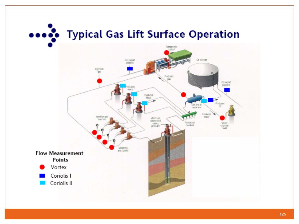
GAS LIFT (1) Gas lift technology increases oil production rate by injection of compressed gas into the lower section of tubing through the casing–tubing annulus and an orifice installed in the tubing string. Upon entering the tubing, the compressed gas affects liquid flow in two ways: (a) the energy of expansion propels (pushes) the oil to the surface and (b) the gas aerates the oil so that the effective density of the fluid is less and, thus, easier to get to the surface.
 the energy of expansion propels (pushes) the oil to the surface and. (b) the gas aerates the oil so that the effective density of the fluid is less and, thus, easier to get to the surface.")
9
SURFACE COMPONENTS SUB-SURFACE COMPONENTS RESERVOIR COMPONENTS

11
Detail Gas Lift Surface Operation
Res. Fluid + Inj. Gas Injected Gas

12
Sistem Sumur Gas Lift Pt Pc Separator Flow Line Gas Injection Line
Wellhead Subsystem : Production subsystem wellhead production choke pressure gauge Injection subsystem injection choke Separator Subsystem: separator manifold pressure gauges flow metering Compressor Subsystem intake system outlet system choke pressure gauge injection rate metering Unloading Gas Lift Mandrells Pt Pc Gas Injection Valve Valve Subsystem Wellbore Subsystem: perforation interval tubing shoe packer

13
Compressor Sub-System
DPgas Compressor Wellhead Separator Pintake Pdischarge Horse Power - DP Qgas

14
Wellhead Sub-System Surface Injection Pressure Production Choke
Gas Injection Production Fluid

15
Gas Lift Valve Sub-System
Pt Pc Gas Injeksi Fluida Produksi Pc = Pt

16
Gas Lift Valve Close condition Open condition Gas Injection Tubing
Pressure Close condition Open condition

17
Kriteria Operasi Sumur Gas Lift
There are four categories of wells in which a gas lift can be considered: High productivity index (PI), high bottom-hole pressure wells High PI, low bottom-hole pressure wells Low PI, high bottom-hole pressure wells Low PI, low bottom-hole pressure wells Wells having a PI of 0.50 or less are classified as low productivity wells. Wells having a PI greater than 0.50 are classified as high productivity wells. High bottom-hole pressures will support a fluid column equal to 70% of the well depth. Low bottom-hole pressures will support a fluid column less than 40% of the well depth.
, high bottom-hole pressure wells. High PI, low bottom-hole pressure wells. Low PI, high bottom-hole pressure wells. Low PI, low bottom-hole pressure wells. Wells having a PI of 0.50 or less are classified as low productivity wells. Wells having a PI greater than 0.50 are classified as high productivity wells. High bottom-hole pressures will support a fluid column equal to 70% of the well depth. Low bottom-hole pressures will support a fluid column less than 40% of the well depth.")
18
2 Types of Gas Lift Operation
Continuous Gas Lift Intermittent Gas Lift A continuous gas lift operation is a steady-state flow of the aerated fluid from the bottom (or near bottom) of the well to the surface. Continuous gas lift method is used in wells with a high PI (0:5 stb=day=psi) and a reasonably high reservoir pressure relative to well depth. Intermittent gas lift operation is characterized by a start-and-stop flow from the bottom (or near bottom) of the well to the surface. This is unsteady state flow. Intermittent gas lift method is suitable to wells with (1) high PI and low reservoir pressure or (2) low PI and low reservoir pressure.
 of the well to the surface. Continuous gas lift method is used in wells with a high PI (0:5 stb=day=psi) and a reasonably high reservoir pressure relative to well depth. Intermittent gas lift operation is characterized by a start-and-stop flow from the bottom (or near bottom) of the well to the surface. This is unsteady state flow. Intermittent gas lift method is suitable to wells with (1) high PI and low reservoir pressure or (2) low PI and low reservoir pressure.")
19
Materi Perencanaan Sumur Gas Lift
This chapter covers basic system engineering design fundamentals for gas lift operations. Relevant topics include the following: Liquid flow analysis for evaluation of gas lift potential Gas flow analysis for determination of lift gas compression requirements Unloading process analysis for spacing subsurface valves Valve characteristics analysis for subsurface valve selection Installation design for continuous and intermittent lift systems.

20
Evaluation of Gas Lift Potential
Evaluation of gas lift potential requires system analyses to determine well operating points for various lift gas availabilities. The principle is based on the fact that there is only one pressure at a given point (node) in any system; no matter, the pressure is estimated based on the information from upstream (inflow) or downstream (outflow). The node of analysis is usually chosen to be the gas injection point inside the tubing, although bottom hole is often used as a solution node.
 in any system; no matter, the pressure is estimated based on the information from upstream (inflow) or downstream (outflow). The node of analysis is usually chosen to be the gas injection point inside the tubing, although bottom hole is often used as a solution node.")
21
Gas Injection Rates Four gas injection rates are significant in the operation of gas lift installations: Injection rates of gas that result in no liquid (oil or water) flow up the tubing. The gas amount is insufficient to lift the liquid. If the gas enters the tubing at an extremely low rate, it will rise to the surface in small semi-spheres (bubbly flow). Injection rates of maximum efficiency where a minimum volume of gas is required to lift a given amount of liquid. Injection rate for maximum liquid flow rate at the ‘‘optimum GLR.’’ Injection rate of no liquid flow because of excessive gas injection. This occurs when the friction (pipe) produced by the gas prevents liquid from entering the tubing
 flow up the tubing. The gas amount is insufficient to lift the liquid. If the gas enters the tubing at an extremely low rate, it will rise to the surface in small semi-spheres (bubbly flow). Injection rates of maximum efficiency where a minimum volume of gas is required to lift a given amount of liquid. Injection rate for maximum liquid flow rate at the ‘‘optimum GLR.’’ Injection rate of no liquid flow because of excessive gas injection. This occurs when the friction (pipe) produced by the gas prevents liquid from entering the tubing.")
22
THE GAS IS INJECTED CONTINUOUSLY TO ANNULUS
CONTINUOUS GAS LIFT THE GAS IS INJECTED CONTINUOUSLY TO ANNULUS

23
Continuous Gas Lift Operation
The tubing is filled with reservoir fluid below the injection point and with the mixture of reservoir fluid and injected gas above the injection point. The pressure relationship is shown in Fig

24
Gas Lift Operation Pressure vs Depth

25
Parameter Design Jumlah gas injeksi yang tersedia
Jumlah gas injeksi yang dibutuhkan Tekanan Gas Injeksi yang dibutuhkan di setiap sumur Tekanan Kompresor yang dibutuhkan

26
Gas Injeksi yang diperlukan
GAS LIFT PERFORMANCE CURVE

27
Availability amount of Gas Injection
Unlimited amount of lift gas Limited amount of gas In a field-scale valuation, if an unlimited amount of lift gas is available for a given gas lift project, the injection rate of gas to individual wells should be optimized to maximize oil production of each well. If only a limited amount of gas is available for the gas lift, the gas should be distributed to individual wells based on predicted well lifting performance, that is, the wells that will produce oil at higher rates at a given amount of lift gas are preferably chosen to receive more lift gas.

28
Kebutuhan Gas Injeksi (1)
Nodal Analysis: IPR Curve Tubing Performance Curve GLR formasi Variasi GLR GLR-total (assume) Qg-inj = Qtotal – Qq-f Plot Qg-inj vs Qliquid
 Qg-inj = Qtotal – Qq-f. Plot Qg-inj vs Qliquid.")
29
Kebutuhan Gas Injeksi (2)
Qg-inj >> maka Qliq >> Pertambahan Qliq makin kecil dengan makin meningkatnya Qg-inj Sampai suatu saat dengan pertambahan Qg-inj, Qliq berkurang Titik puncak dimana Qliq maksimum disebut sebagai Qoptimum

30
Unlimited Gas Injection Case
If an unlimited amount of gas lift gas is available for a well, the well should receive a lift gas injection rate that yields the optimum GLR in the tubing so that the flowing bottom-hole pressure is minimized, and thus, oil production is maximized. The optimum GLR is liquid flow rate dependent and can be found from traditional gradient curves such as those generated by Gilbert (Gilbert, 1954).
.")
31
Unlimited Gas Injection Case
After the system analysis is completed with the optimum GLRs in the tubing above the injection point, the expected liquid production rate (well potential) is known. The required injection GLR to the well can be calculated by
 is known. The required injection GLR to the well can be calculated by.")
32
Limited amount of gas injection
If a limited amount of gas lift gas is available for a well, the well potential should be estimated based on GLR expressed as

33
Gas Flow Rate Requirement
The total gas flow rate of the compression station should be designed on the basis of gas lift at peak operating condition for all the wells with a safety factor for system leak consideration, that is, where qg = total output gas flow rate of the compression station, scf/day Sf = safety factor, 1.05 or higher Nw = number of wells

34
Point of Injection

35
Output Gas Pressure Requirement (1)
Kickoff of a dead well (non-natural flowing) requires much higher compressor output pressures than the ultimate goal of steady production (either by continuous gas lift or by intermittent gas lift operations).Mobil compressor trailers are used for the kickoff operations.
 requires much higher compressor output pressures than the ultimate goal of steady production (either by continuous gas lift or by intermittent gas lift operations).Mobil compressor trailers are used for the kickoff operations.")
36
Output Gas Pressure Requirement (2)
DPgas Compressor Wellhead Separator Pintake Pdischarge Horse Power - DP Qgas The output pressure of the compression station should be designed on the basis of the gas distribution pressure under normal flow conditions, not the kickoff conditions. It can be expressed as

37
COMPRESSOR

38
Output Gas Pressure Requirement (3)
The injection pressure at valve depth in the casing side can be expressed as: It is a common practice to use Dpv = 100 psi. The required size of the orifice can be determined using the choke-flow equations presented in Subsection Pt Pc Gas Injeksi Fluida Produksi Pc = Pt

39
Tekanan Tubing @ Valve Gas Lift
tubing Pwf

40
Output Gas Pressure Requirement (4)
Accurate determination of the surface injection pressure pc,s requires rigorous methods such as the Cullender and Smith method (Katz et al., 1959). However, because of the large cross-sectional area of the annular space, the frictional pressure losses are often negligible. Then the average temperature and compressibility factor model degenerates to (Economides et al., 1994) Production Choke Injection Surface Injection Pressure Wellhead Gas Injection Production Fluid
. However, because of the large cross-sectional area of the annular space, the frictional pressure losses are often negligible. Then the average temperature and compressibility factor model degenerates to (Economides et al., 1994) Production. Choke. Injection. Surface Injection. Pressure. Wellhead. Gas Injection. Production Fluid.")
41
Up-Stream Choke / Injection Choke
The pressure upstream of the injection choke depends on flow condition at the choke, that is, sonic or subsonic flow. Whether a sonic flow exists depends on a downstream-toupstream pressure ratio. If this pressure ratio is less than a critical pressure ratio, sonic (critical) flow exists. If this pressure ratio is greater than or equal to the critical pressure ratio, subsonic (subcritical) flow exists. The critical pressure ratio through chokes is expressed as Production Choke Injection Surface Injection Pressure Wellhead Gas Injection Production Fluid
 flow exists. If this pressure ratio is greater than or equal to the critical pressure ratio, subsonic (subcritical) flow exists. The critical pressure ratio through chokes is expressed as. Production. Choke. Injection. Surface Injection. Pressure. Wellhead. Gas Injection. Production Fluid.")
42
Gas Lift Injection Parameters
Compressor Pressure Pwf

43
Point of Injection

44
Point of Balanced

45
Unloading Valves Design
Unloading Process Gas Lift Wells

46
Persiapan Operasi Sumur Gas Lift

47
TAHAP O Katup Unloading sudah dipasang.
Choke Tutup Valve 1 : Terbuka Valve 2 : Terbuka Valve 3 : Terbuka Valve 4 : Terbuka Permukaan Killing fluid No flow Katup Unloading sudah dipasang. Sumur masih diisi killing fluid Fluida produksi masih belum mengalir ke dalam tubing

48
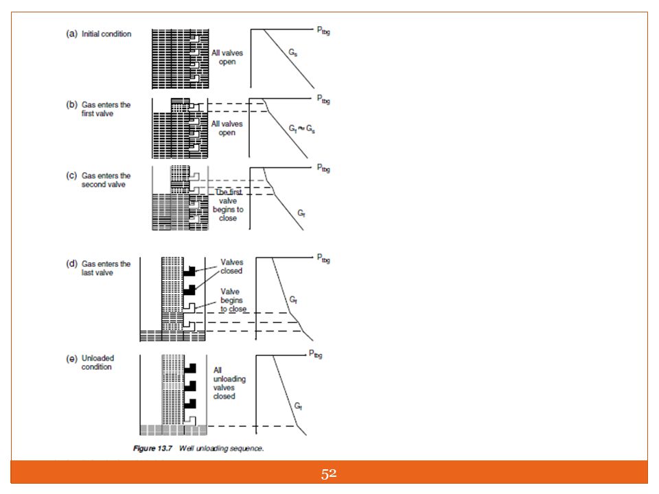
Tahap I Pada Gambar 1 ditunjukkan penampang sumur yang siap dilakukan proses pengosongan (unloading). Pada tubing telah dipasang empat katup, yang terdiri dari 3 katup, yaitu katup (1), (2) dan (3), yang akan berfungsi sebagai katup unloading. Sedangkan katup (4) akan berfungsi sebagai katup operasi. Sebelum dilakukan injeksi semua katup dalam keadaan terbuka. Sumur berisi cairan work-over, ditunjukkan dengan warna biru, dan puncak cairan berada diatas katup unloading (1). Gas mulai diinjeksikan, maka gas akan menekan permukaan cairan work over kebawah, dan penurunan permukaan cairan ini akan mencapai katup unloading (1). Pada saat ini gas akan mengalir dalam tubing melalui katup (1) yang terbuka. No flow Permukaan Killing fluid Valve 1 : Terbuka Valve 2 : Terbuka Valve 3 : Terbuka Valve 4 : Terbuka
. Pada tubing telah dipasang empat katup, yang terdiri dari 3 katup, yaitu katup (1), (2) dan (3), yang akan berfungsi sebagai katup unloading. Sedangkan katup (4) akan berfungsi sebagai katup operasi. Sebelum dilakukan injeksi semua katup dalam keadaan terbuka. Sumur berisi cairan work-over, ditunjukkan dengan warna biru, dan puncak cairan berada diatas katup unloading (1). Gas mulai diinjeksikan, maka gas akan menekan permukaan cairan work over kebawah, dan penurunan permukaan cairan ini akan mencapai katup unloading (1). Pada saat ini gas akan mengalir dalam tubing melalui katup (1) yang terbuka. No flow. Permukaan. Killing fluid. Valve 1 : Terbuka. Valve 2 : Terbuka. Valve 3 : Terbuka. Valve 4 : Terbuka.")
49
Tahap II Pada Gambar 2 gas injeksi mendorong permukaan cairan work-over, dan telah me-lampaui katup unloading (1) dan mencapai katup unloading (2). Pada saat ini katup unloading (1) tertutup dan gas injeksi mendorong permukaan cairan kebawah. Bagian bawah tubing yang semula berisi cairan work-over ditempati oleh fluida for-masi. Pada saat ini gas akan masuk kedalam tubing, melalui katup unloading (2) yang terbuka. Dengan masuknya gas injeksi tersebut kedalam tubing maka kolom cairan dalam tubing akan lebih ringan dan aliran cairan work over ke permukaan akan berlanjut. Valve 1 : Tertutup Permukaan Killing fluid Valve 2 : Terbuka Valve 3 : Terbuka Valve 4 : Terbuka Permukaan Fluida Res.
 dan mencapai katup unloading (2). Pada saat ini katup unloading (1) tertutup dan gas injeksi mendorong permukaan cairan kebawah. Bagian bawah tubing yang semula berisi cairan work-over ditempati oleh fluida for-masi. Pada saat ini gas akan masuk kedalam tubing, melalui katup unloading (2) yang terbuka. Dengan masuknya gas injeksi tersebut kedalam tubing maka kolom cairan dalam tubing akan lebih ringan dan aliran cairan work over ke permukaan akan berlanjut. Valve 1 : Tertutup. Permukaan. Killing fluid. Valve 2 : Terbuka. Valve 3 : Terbuka. Valve 4 : Terbuka. Permukaan. Fluida Res.")
50
Tahap III Pada Gambar 3 gas injeksi mendorong permukaan cairan work-over, sampai me-lampaui katup unloading (1), (2) dan (3). Setiap saat permukaan kolom cairan work-over mencapai katup unloading, maka gas injeksi akan mengalir masuk kedalam tubing dan aliran cairan work-over dalam tubing akan tetap berlangsung. Jika per-mukaan kolom cairan work-over mencapai katup unlaoding (3), maka katup unloading (2) akan tertutup, dan gas injeksi akan masuk melalui katup unloading (3). Selama ini pula permukaan cairan formasi akan bergerak ke permukaan. Pada saat cairan work-over mencapai katup terakhir, yaitu katup operasi (4), maka katup unloading (3) akan tertutup dan seluruh cairan work-over telah terangkat semua ke permukaan, dan hanya katup operasi yang terbuka. Valve 1 : Tertutup Permukaan Fluida Res. Valve 2 : Tertutup Valve 3 : Tertutup Permukaan Killing fluid Valve 4 : Terbuka
, (2) dan (3). Setiap saat permukaan kolom cairan work-over mencapai katup unloading, maka gas injeksi akan mengalir masuk kedalam tubing dan aliran cairan work-over dalam tubing akan tetap berlangsung. Jika per-mukaan kolom cairan work-over mencapai katup unlaoding (3), maka katup unloading (2) akan tertutup, dan gas injeksi akan masuk melalui katup unloading (3). Selama ini pula permukaan cairan formasi akan bergerak ke permukaan. Pada saat cairan work-over mencapai katup terakhir, yaitu katup operasi (4), maka katup unloading (3) akan tertutup dan seluruh cairan work-over telah terangkat semua ke permukaan, dan hanya katup operasi yang terbuka. Valve 1 : Tertutup. Permukaan. Fluida Res. Valve 2 : Tertutup. Valve 3 : Tertutup. Permukaan. Killing fluid. Valve 4 : Terbuka.")
51
TAHAP IV Pada Gambar 4 ditunjukkan bahwa semua cairan work-over telah terangkat dan sumur berproduksi secara sembur buatan. Katup operasi (4) akan tetap terbuka, sebagai jalan masuk gas injeksi kedalam tubing. Katup ini diharapkan dapat bekerja dalam waktu yang lama. Dimasa mendatang akan terjadi perubahan perbandingan gas-cairan dari formasi, yang cenderung menurun serta peningkatan produksi air, maka jumlah gas injeksi dapat ditingkatkan dan diharapkan katup injeksi dapat menampung peningkatan laju injeksi gas tersebut. Dengan demikian pemilihan ukuran katup injeksi perlu direncanakan dengan baik. Fluida Produksi Valve 1 : Tertutup Valve 2 : Tertutup Valve 3 : Tertutup Valve 4 : Terbuka
 akan tetap terbuka, sebagai jalan masuk gas injeksi kedalam tubing. Katup ini diharapkan dapat bekerja dalam waktu yang lama. Dimasa mendatang akan terjadi perubahan perbandingan gas-cairan dari formasi, yang cenderung menurun serta peningkatan produksi air, maka jumlah gas injeksi dapat ditingkatkan dan diharapkan katup injeksi dapat menampung peningkatan laju injeksi gas tersebut. Dengan demikian pemilihan ukuran katup injeksi perlu direncanakan dengan baik. Fluida. Produksi. Valve 1 : Tertutup. Valve 2 : Tertutup. Valve 3 : Tertutup. Valve 4 : Terbuka.")
53
Unloading Valves Design
gas lift Valve gas lift Valve Mechanics

54
Gas Lift Valve

55
Gas Lift Valve

56
} Contoh Penampang Sumur Gas Lift Gas Lift Mandrell Gas Lift Valves
Mandrell + Dummy Valves Mandrell + Valves Valves Operating Conditions: Casing pressure Test Rack Opening Pressure Port Size Lab. Jenis Valves

57
Gas Lift Valve Pt Pc Gas Injeksi Fluida Produksi Pc = Pt

58
Penampang Gas Lift Valve

59
Jenis Gas Lift Valves

60
Gas Lift Valve Close condition Open condition Gas Injection Tubing
Pressure Close condition Open condition

61
Closing & opening pressure
Valve Mechanics Mekanika valve Closing & opening pressure

62
Mekanika Valve (Membuka+Menutup)
Dome berisi gas Nitrogen yang mempunyai tekanan tertentu. Gas Nitrogen ini menekan bagian dasar dome, Pd, pada luas penampang bellow, Ab Port terbuka untuk dilalui gas masuk kedalam tubing, jika ujung stem tidak menempel pada port. Jika gaya membuka sedikit lebih besar dari gaya menutup.

63
Posisi Valve Tertutup Gaya menutup= Fc = Pd Ab
Perkalian antara tekanan dalam dome, Pd, dengan luas penampang bellow, Ab, menghasilkan gaya kebawah yang mendorong stem dan ujung stem kebawah, sehingga menutup port. Gaya ini disebut sebagai gaya menutup. Gaya menutup= Fc = Pd Ab Gas Lift - Design

64
Posisi Valve Terbuka Gaya membuka ini berasal dari tekanan gas injeksi dari anulus, Pc yang menekan bellow ke atas, pada luas penampang efektif sebesar (Ab-Ap) serta tekanan fluida dari tubing, Pt (melalui port) yang menekan ujung stem keatas. Gaya membuka = Pc (Ab - Ap) + Pt Ap Gas Lift - Design
 serta tekanan fluida dari tubing, Pt (melalui port) yang menekan ujung stem keatas. Gaya membuka = Pc (Ab - Ap) + Pt Ap. Gas Lift - Design.")
65
Keseimbangan Gaya Membuka dan Menutup
Dalam keadaan seimbang, yaitu sesaat katup akan membuka, gaya membuka sama dengan gaya menutup, hal ini dapat dinyatakan sebagai berikut: Untuk tekanan tubing, Pt tertentu, gas akan mengalir kedalam katup apabila: Jika persamaan (2) dibagi dengan Ab, maka diperoleh persamaan berikut: Gas Lift - Design
 dibagi dengan Ab, maka diperoleh persamaan berikut: Gas Lift - Design.")
66
Penentuan Tekanan Injeksi Katup Terbuka/Tertutup
Apabila R = Ap/Ab, maka Harga tekanan injeksi, Pc, dapat ditentukan dengan persamaan berikut : Persamaan diatas dapat digunakan untuk menentukan tekanan gas injeksi yang dibutuhkan untuk membuka katup dibawah kondisi operasi. Gas Lift - Design

67
Contoh Soal Katup sembur buatan ditempatkan di kedalaman 6000 ft.
Tekanan dome dan tekanan tubing di kedalaman tersebut masing-masing sebesar 700 psi dan 500 psi. Apabila Ab katup sebesar 1.0 in2 dan Ap = 0.1 in2, tentukan tekanan gas di annulus yang diperlukan untuk membuka katup. Perhitungan: R = Ap/Ab = 0.1/1.0 = 0.1 Pd = 700 psi Pt = 500 psi Dengan menggunakan persamaan (5), tekanan gas injeksi yang diperlukan untuk membuka katup sebesar: Pc = ( (0.1) / ( ) = 722 psi Gas Lift - Design
, tekanan gas injeksi yang diperlukan untuk membuka katup sebesar: Pc = ( (0.1) / ( ) = 722 psi. Gas Lift - Design.")
68
Penentuan Tekanan Dome
Pd = ? Pada Temperature Di kedalaman Valve Test Rack Opening Pressure Diubah menjadi Tekanan pada Temperatur Bengkel Gas Lift - Design

69
DOME PADA GAS LIFT VALVE
Dome pada Gas Lift Valve, diisi gas Nitrogen sejumlah mole tertentu, sehingga dapat memberikan tekanan tutup valve yang sesuai. Sesuai dengan P V=Z n R T P-dome Vol. dome Temperatur di sekitar dome Gas Lift - Design

70
Penentuan Tekanan Dome
Tekanan TD = Pd Tekanan D = Pc Test Rack (di Bengkel) Tekanan TD convert Tekanan 60 oF (Tabel 5-3) Tekanan buka valve, pvo Gradien tubing @TD Gradien gas injeksi Tabel 5-3 Gas Lift - Design
 Tekanan TD. convert. Tekanan 60 oF. (Tabel 5-3) Tekanan buka valve, pvo. Gradien Gradien gas injeksi. Tabel 5-3. Gas Lift - Design.")
71
Temperatur pada Valve T-surface Gradient Temperatur Aliran Gradient
Geothermal (oF/ft) Retreivable valve Non-Retreivable valve T-bottom Gas Lift - Design
 Retreivable valve. Non-Retreivable. valve. T-bottom. Gas Lift - Design.")
72
Penentuan Opening/Closing Pressure di Bengkel

73
Penentuan Test Rack Opening Pressure
P1 = Pc P2 = 0 Gas Lift - Design

74
Ptro (1) Keseimbangan Gaya Buka dan Gaya Tutup, pada Pt = Patm :
Dimana Pvc = tekanan tutup di bengkel Jika R = Ap/Ab, maka Maka P-dome di bengkel : Gas Lift - Design

75
Ptro (2) Gaya Buka hanya dipengaruhi oleh Pvc, yaitu:
Pd di set pada temperatur bengkel (60oF) Perlu dilakukan koreksi terhadap temperatur pada kedalaman valve Gas Lift - Design
 Perlu dilakukan koreksi terhadap temperatur pada kedalaman valve. Gas Lift - Design.")
76
Faktor Koreksi Tekanan Gas Nitrogen Dalam Dome
(pada Temperatur Bengkel 60 oF) PV = ZnRT @ Tv PV = ZnRT @ 60 oF Gas Lift - Design
 PV = Tv. PV = 60 oF. Gas Lift - Design.")
77
Perhitungan Tekanan @ Bellow secara Analitis
Gas Lift - Design P(x) = tekanan rata-rata yang bekerja pada bellow Pvi = P(x) yang diperlukan untuk membuka katup z = pergerakan stem dari posisi tertutup k = cp/cv Ab = luas permukaan bellow Pdi = tekanan dome awal Pd(x)=tekanan dome jika stem bergerak sejauh x
 = tekanan rata-rata yang bekerja. pada bellow. Pvi = P(x) yang diperlukan untuk. membuka katup. z = pergerakan stem dari posisi tertutup. k = cp/cv. Ab = luas permukaan bellow. Pdi = tekanan dome awal. Pd(x)=tekanan dome jika stem bergerak. sejauh x.")
78
Penentuan Ukuran Port Valve
Gas Lift - Design Laju Alir pada kondisi kritik : Q = laju alir gas, MCF/d Cd = discharge coefficient Ap = luas penampang port Pu = tekanan injeksi gas dalam annulus, psia k = cp/cv R = perbandingan antara tekanan upstream dengan downstream T = temperatur aliran gg = specific gravity gas Atau dengan menggunakan Grafik, yang dibuat pada kondisi Specific Gravity gas = 0.65 Temperatur alir = 60 oF Tekanan dasar = psia k = cp/cv = 1.27 Discharge coeficient = 0.865

79
Penentuan Ukuran Port : R
Berdasarkan rate injeksi (di permukaan – Mscf/d), qgi, sc tentukan rate TD Berdasarkan Pt dan Pc, gunakan Gambar 5-22, untuk menentukan ukuran Port Pt = downstream press Pc = upstream press Gas Lift - Design
, qgi, sc tentukan rate TD. Berdasarkan Pt dan Pc, gunakan Gambar 5-22, untuk menentukan ukuran Port. Pt = downstream press. Pc = upstream press. Gas Lift - Design.")
80
Unloading Valve Design
Penempatan valve unloading Valve spacing

81
However, the basic objective should be the same:
Various methods are being used in the industry for designing depths of valves of different types. They are the universal design method, the API-recommended method, the fallback method, and the percent load method. However, the basic objective should be the same: 1. To be able to open unloading valves with kickoff and injection operating pressures 2. To ensure single-point injection during unloading and normal operating conditions 3. To inject gas as deep as possible

82
No matter which method is used, the following principles apply:
The design tubing pressure at valve depth is between gas injection pressure (loaded condition) and the minimum tubing pressure (fully unloaded condition). Depth of the first valve is designed on the basis of kickoff pressure from a special compressor for well kickoff operations. Depths of other valves are designed on the basis of injection operating pressure. Kickoff casing pressure margin, injection operating casing pressure margin, and tubing transfer pressure margin are used to consider the following effects: Pressure drop across the valve Tubing pressure effect of the upper valve Nonlinearity of the tubing flow gradient curve.
 and the minimum tubing pressure (fully unloaded condition). Depth of the first valve is designed on the basis of kickoff pressure from a special compressor for well kickoff operations. Depths of other valves are designed on the basis of injection operating pressure. Kickoff casing pressure margin, injection operating casing pressure margin, and tubing transfer pressure margin are used to consider the following effects: Pressure drop across the valve. Tubing pressure effect of the upper valve. Nonlinearity of the tubing flow gradient curve.")
83
Test II : Kamis, 26 Februari 2009

Presentasi serupa


>")

>")
>")


>")


, specific volume (V), and temperature (T) will be presented for a pure substance. A pure substance.>")

