Upload presentasi
Presentasi sedang didownload. Silahkan tunggu

1
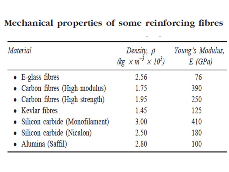
4. FIBER-REINFORCED COMPOSITE
Komposit ini berupa serat/fiber yang ditanam dalam matriks yang biasanya bersifat lebih lunak, sehingga dihasilkan produk dengan rasio strength/weight yang tinggi. Material matriks meneruskan beban kepada serat/fiber yang berfungsi menyerap stress. Untuk mendapatkan strengthening dan stiffening yang efektif, maka perlu diketahui panjang kritik dari serat.

2
PENGARUH PANJANG SERAT
Sifat mekanik fiber-reinforced composite dipengaruhi oleh sifat serat dan bagaimana beban diteruskan/transmitted pada serat. Transmittance beban dipengaruhi oleh besarnya ikatan interfacial antara serat dan matriks. Dibawah stress tertentu, ikatan antara serat dan matriks berakhir di ujung serat, sehingga pola deformasi matriks yang terjadi adalah seperti gambar di slide berikut.

3
The deformation pattern in the matrix surrounding of fiber, subjected to an applied tensile

4
Ada panjang kritik tertentu yang diperlukan agar penguatan oleh serat menjadi efektif.
Panjang kritik lc tergantung pada diameter serat d dan tensile strength *f , juga pada kekuatan ikatan serat- matriks c, menurut persamaan berikut: (3) Contoh: untuk kombinasi kaca dan serat karbon, lc = 1 mm (= 20 – 150 kali dimeternya)
 Contoh: untuk kombinasi kaca dan serat karbon, lc = 1 mm (= 20 – 150 kali dimeternya)")
5
Stress–position profiles when fiber length is equal to the critical length

6
Stress–position profiles when fiber length is greater than the critical length

7
Stress–position profiles when fiber length is less than the critical length

8
Kekuatan komposit ini disebabkan oleh ikatan antara serat penguat dengan matriks.
Rasio panjang/diameter (disebut aspect ratio) dari serat penguat akan mempengaruhi sifat-sifat komposit. Semakin besar aspect ratio, maka semakin kuat komposit. Oleh karena itu untuk komposit konstruksi, serat yang panjang lebih baik daripada serat pendek. Akan tetapi serat panjang lebih sulit diproduksi daripada serat pendek Serat pendek lebih mudah diatur dalam matriks, tetapi efek penguatannya kurang baik dibandingkan dengan serat panjang.
 dari serat penguat akan mempengaruhi sifat-sifat komposit. Semakin besar aspect ratio, maka semakin kuat komposit. Oleh karena itu untuk komposit konstruksi, serat yang panjang lebih baik daripada serat pendek. Akan tetapi serat panjang lebih sulit diproduksi daripada serat pendek. Serat pendek lebih mudah diatur dalam matriks, tetapi efek penguatannya kurang baik dibandingkan dengan serat panjang.")
9
Oleh karena itu perlu adanya trade-off antara jenis serat yang digunakan dengan efek penguatan yang diinginkan. Jumlah serat juga berpengaruh terhadap kekuatan komposit; semakin banyak jumlah serat, maka semakin kuat komposit yang dihasilkan. Batas maksimum jumlah serat adalah sekitar 80% dari volume komposit. Jika jumlah serat > 80% maka matriks tidak dapat menutupi seluruh serat dengan sempurna. Serat dengan l >> lc (normal: l > 15 lc) disebut kontinyu, sementara Serat dengan l < 15 lc disebut diskontinyu. Jika panjang serat < lc, maka komposit yang dihasilkan pada dasarnya sama dengan particulate composites.
 disebut kontinyu, sementara Serat dengan l < 15 lc disebut diskontinyu. Jika panjang serat < lc, maka komposit yang dihasilkan pada dasarnya sama dengan particulate composites.")
12
PENGARUH ORIENTASI DAN KONSENTRASI SERAT
Susunan atau orientasi serat terhadap serat lainnya, konsentrasi serat, dan keseragaman distribusi akan mempengaruhi kekuatan dan sifat-sifat lainnya dari fiber- reinforced composites. Ada dua orientasi yang ekstrim: (i) sejajar teratur, dan (ii) acak seluruhnya. Serat kontinyu biasanya sejajar teratur, sementara serat diskontinyu dapat teratur atau acak.
 sejajar teratur, dan (ii) acak seluruhnya. Serat kontinyu biasanya sejajar teratur, sementara serat diskontinyu dapat teratur atau acak.")
13
Sifat mekanik dari komposit jenis ini tergantung pada:
Perilaku stress-strain dari serat dan matriks Fraksi volume masing-masing komponen Arah stress atau beban pada material komposit. Sifat-sifat komposit yang memiliki fiber yang teratur sangat anisotropic, yaitu besarnya nilai sifat tergantung pada arah pengukuran. Kita perhatikan perilaku stress-strain apabila stress dikena- kan terhadap material sejajar dengan arah serat, yaitu arah longitudinal, seperti ditunjukkan pada Gambar (a).
.")
14
Ilustrasi dari fiber-reinforced composites yang (a) kontinyu dan teratur, (b) diskontinyu dan teratur, and (c) diskontinyu dan acak
 kontinyu dan teratur, (b) diskontinyu dan teratur, and (c) diskontinyu dan acak")
15
Misal perilaku stress vs strain dari fasa fiber dan matriks sebagaimana ditunjukkan pada gambar di slide berikut. Dalam hal ini fiber bersifat sangat rapuh/brittle dan matriks bersifat cukup elastis/ductile. Pada gambar tersebut: *f : fracture strength in tension for fiber *m : fracture strength in tension for matrix *f : fracture strain in tension for fiber *m : fracture strain in tension for matrix

16
(a) Schematic stress–strain curves for brittle fiber and ductile matrix materials. Fracture stresses and strains for both materials are noted. (b) Schematic stress–strain curve for an aligned fiber-reinforced composite that is exposed to a uniaxial stress applied in the direction of alignment; curves for the fiber and matrix materials shown in part (a) are also superimposed.
 Schematic stress–strain curve for an aligned fiber-reinforced composite that is exposed to a uniaxial stress applied in the direction of alignment; curves for the fiber and matrix materials shown in part (a) are also superimposed..")
17
Perilaku stress-strain dari material komposit ditunjukkan pada gambar (b).
Di daerah Stage I, fiber dan matriks mengalami deformasi secara elastis; perilaku stress-strain biasanya berupa kurva linier. Matriks mengalami deformasi plastis, sedangkan fiber mengalami stretch elastis. Di daerah Stage II, hubungan antara stress dan strain hampir linier dengan slope yang lebih kecil daripada stage I. The onset of composite failure ditandai dengan saat fiber mulai rusak, yaitu pada saat strain = *f. Pada kondisi ini komposit belum rusak benar, karena Tidak semua fiber rusak pada saat yang sama, Meskipun sebagian fiber telah rusak, tetapi matriks masih utuh karena *f < *m

18
Let us now consider the elastic behavior of a continuous and oriented fibrous composite that is loaded in the direction of fiber alignment. First, it is assumed that the fiber–matrix interfacial bond is very good, such that deformation of both matrix and fibers is the same (an isostrain situation). Under these conditions, the total load sustained by the composite Fc is equal to the sum of the loads carried by the matrix phase Fm and the fiber phase Ff, or (4)
. Under these conditions, the total load sustained by the composite Fc is equal to the sum of the loads carried by the matrix phase Fm and the fiber phase Ff, or. (4)")
19
From the definition of stress:
Equation (4) can be written as: (5) dividing through by the total cross-sectional area of the composite, we have: (6) where Am/Ac and Af/Ac are the area fractions of the matrix and fiber phases, respectively.
 can be written as: (5) dividing through by the total cross-sectional area of the composite, we have: (6) where Am/Ac and Af/Ac are the area fractions of the matrix and fiber phases, respectively.")
20
If the composite, matrix, and fiber phase lengths are all equal, Am/Ac is equivalent to the volume fraction of the matrix, Vm, and Af/Ac and likewise for the fibers, Vf = Af/Ac. Eq. (6) now becomes: (7) The previous assumption of an isostrain state means that (8) and when each term in eq. (7) is divided by its respective strain (9)
 now becomes: (7) The previous assumption of an isostrain state means that. (8) and when each term in eq. (7) is divided by its respective strain. (9)")
21
Furthermore, if composite, matrix, and fiber deformations are all elastic, then
the E’s being the moduli of elasticity for the respective phases. Substitution into eq. (6) yields an expression for the modulus of elasticity of a continuous and aligned fibrous composite in the direction of alignment (or longitudinal direction), as (10.a) (10.b)
 yields an expression for the modulus of elasticity of a continuous and aligned fibrous composite in the direction of alignment (or longitudinal direction), as. (10.a) (10.b)")
22
Thus, Ecl is equal to the volume-fraction weighted average of the moduli of elasticity of the fiber and matrix phases. Other properties, including density, also have this dependence on volume fractions. for longitudinal loading, that the ratio of the load carried by the fibers to that carried by the matrix is (11)
")
23
EXAMPLE 1 A continuous and aligned glass fiber-reinforced composite consists of 40 vol% of glass fibers having a modulus of elasticity of 69 GPa and 60 vol% of a polyester resin that, when hardened, displays a modulus of 3.4 GPa. Compute the modulus of elasticity of this composite in the longitudinal direction. If the cross-sectional area is 250 mm2 and a stress of 50 MPa is applied in this longitudinal direction, compute the magnitude of the load carried by each of the fiber and matrix phases. Determine the strain that is sustained by each phase when the stress in part (b) is applied.
 is applied.")
24
SOLUTION The modulus of elasticity of the composite is calculated using eq. (10.a): = 30 GPa To solve this portion of the problem, first find the ratio of fiber load to matrix load, using eq. (11); thus,
; thus,")
25
In addition, the total force sustained by the composite Fc may be computed from the applied stress and total composite cross-sectional area Ac according to this total load is just the sum of the loads carried by fiber and matrix phases; that is,

26
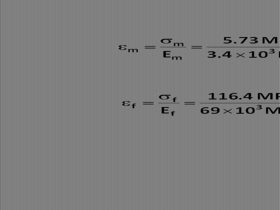
The stress for both fiber and matrix phases must first be calculated
The stress for both fiber and matrix phases must first be calculated. Then, by using the elastic modulus for each (from part a), the strain values may be determined.
, the strain values may be determined.")
28
A continuous and oriented fiber composite may be loaded in the transverse direction; that is, the load is applied at a 90 angle to the direction of fiber alignment. For this situation the stress to which the composite as well as both phases are exposed is the same, or (12) This is termed an isostress state. Also, the strain or defor-mation of the entire composite is (13)
 This is termed an isostress state. Also, the strain or defor-mation of the entire composite is. (13)")
29
But since Substituting the above three to equations (13) yields: (14)
 yields: (14)")
30
where is Ecl the modulus of elasticity in the transverse direction.
Now, dividing through by yields (15) which reduces to (16)
 which reduces to. (16)")
31
EXAMPLE 2 Compute the elastic modulus of the composite material described in Example 1, but assume that the stress is applied perpendicular to the direction of fiber alignment. SOLUTION According to eq. (13):
:")
32
We now consider the strength characteristics of continuous and aligned fiber-reinforced composites that are loaded in the longitudinal direction. Under these circumstances, strength is normally taken as the maximum stress on the stress–strain curve. Often this point corresponds to fiber fracture, and marks the onset of composite failure. Table 1 lists typical longitudinal tensile strength values for three common fibrous composites. Failure of this type of composite material is a relatively complex process, and several different failure modes are possible. The mode that operates for a specific composite will depend on fiber and matrix properties, and the nature and strength of the fiber–matrix interfacial bond.

33
Onset of composite failure

34
The Fiber Content for Each Is Approximately 50 Vol%
Table 1. Typical Longitudinal and Transverse Tensile Strengths for Three Unidirectional Fiber-Reinforced Composites. The Fiber Content for Each Is Approximately 50 Vol%

35
If we assume that . f <
If we assume that *f < *m, which is the usual case, then fibers will fail before the matrix. Once the fibers have fractured, the majority of the load that was borne by the fibers is now transferred to the matrix. This being the case, it is possible to adapt the expression for the stress on this type of composite, eq. (7), into the following expression for the longitudinal strength of the composite *cl (17) Here ’m is the stress in the matrix at fiber failure and, *f as previously, is the fiber tensile strength.
, into the following expression for the longitudinal strength of the composite *cl. (17) Here ’m is the stress in the matrix at fiber failure and, *f as previously, is the fiber tensile strength.")
36
’m

37
The strengths of continuous and unidirectional fibrous composites are highly anisotropic, and such composites are normally designed to be loaded along the high strength, longitudinal direction. However, during in-service applications transverse tensile loads may also be present. Under these circumstances, premature failure may result inasmuch as transverse strength is usually extremely low—it sometimes lies below the tensile strength of the matrix. Thus, in actual fact, the reinforcing effect of the fibers is a negative one. Typical transverse tensile strengths for three unidirectional composites are contained in Table 1.

38
Whereas longitudinal strength is dominated by fiber strength, a variety of factors will have a significant influence on the transverse strength; these factors include properties of both the fiber and matrix, the fiber–matrix bond strength, and the presence of voids. Measures that have been employed to improve the transverse strength of these composites usually involve modifying properties of the matrix.

39
Even though reinforcement efficiency is lower for dis- continuous than for continuous fibers, discontinuous and aligned fiber composites are becoming increasingly more important in the commercial market. Chopped glass fibers are used most extensively; carbon and aramid discontinuous fibers are also employed. These short fiber composites can be produced having moduli of elasticity and tensile strengths that approach 90% and 50%, respectively, of their continuous fiber counterparts.

40
For a discontinuous and aligned fiber composite having a uniform distribution of fibers and in which l > lc, the longitudinal strength (*cd) is given by the relationship: (18) where *f and ’m represent, respectively, the fracture strength of the fiber and the matrix when the composite fails. If l < lc then the longitudinal strength is given by (19) where d is the fiber diameter and c is the smaller of either the fiber–matrix bond strength or the matrix shear yield strength.
 where *f and ’m represent, respectively, the fracture strength of the fiber and the matrix when the composite fails. If l < lc then the longitudinal strength is given by. (19) where d is the fiber diameter and c is the smaller of either the fiber–matrix bond strength or the matrix shear yield strength.")
41
Normally, when the fiber orientation is random, short and discontinuous fibers are used.
Under these circumstances, a “rule-of-mixtures” expression for the elastic modulus similar to eq. (10.a) may be utilized, as follows: (20) In this expression, K is a fiber efficiency parameter that depends on and the Ef/Em ratio. Of course, its magnitude will be less than unity, usually in the range 0.1 to 0.6.
 may be utilized, as follows: (20) In this expression, K is a fiber efficiency parameter that depends on and the Ef/Em ratio. Of course, its magnitude will be less than unity, usually in the range 0.1 to 0.6.")
42
Thus, for random fiber reinforcement (as with oriented), the modulus increases in some proportion of the volume fraction of fiber. Table 2, which gives some of the mechanical properties of unreinforced and reinforced polycarbonates for dis- continuous and randomly oriented glass fibers, provides an idea of the magnitude of the reinforcement that is possible.

43
Table 2. Properties of Unreinforced and Reinforced Polycarbonates with Randomly Oriented Glass Fibers

44
Table 3. Reinforcement Efficiency of Fiber-Reinforced Composites for Several Fiber Orientations and at Various Directions of Stress Application

Presentasi serupa

>")


>")
