Upload presentasi
Presentasi sedang didownload. Silahkan tunggu

1
PERMEABILITAS Yulvi Zaika

2
SIKLUS HIDROLOGI

3
Muka Air Tanah

4
AQUIFER

5
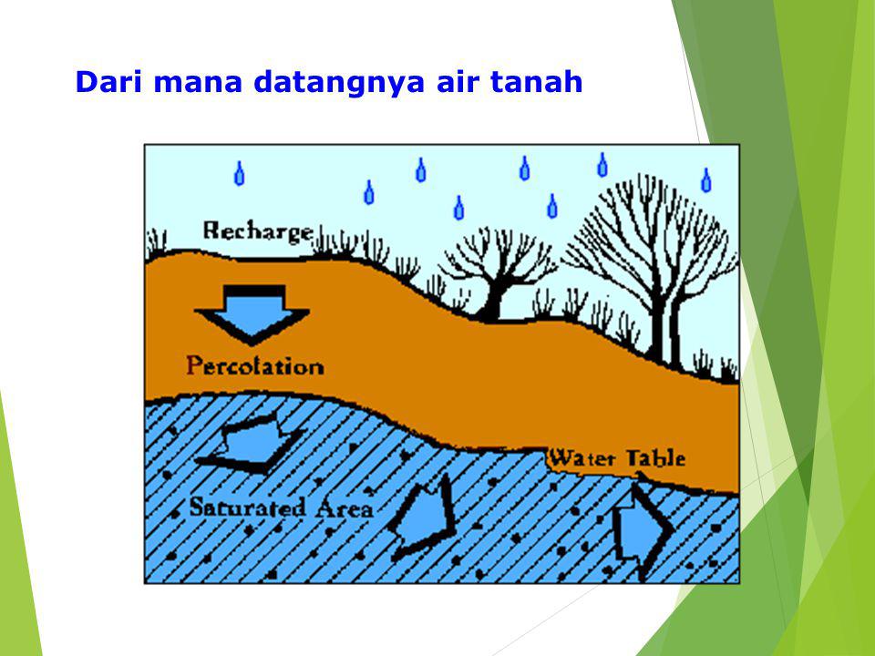
Dari mana datangnya air tanah
6
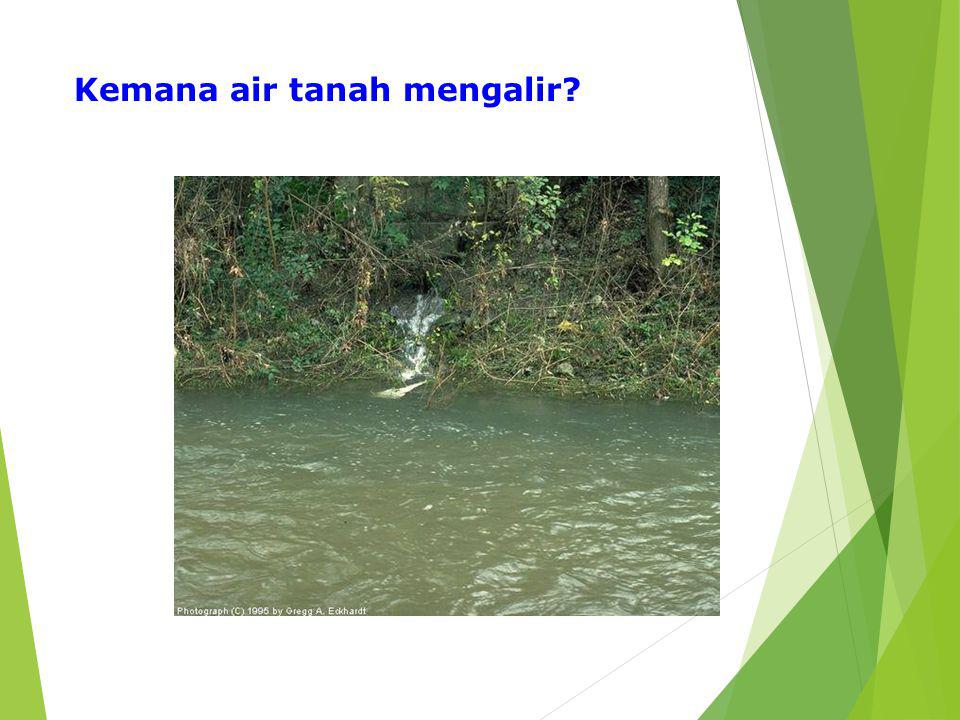
Kemana air tanah mengalir?
7
Interaksi air tanah dan air permukaan

8
Aliran Shallow, unconfined aquifers often follow the same flow patterns as the watershed above them, as seen in the illustration at right. Deeper, confined aquifers may be part of a different flow system.

9
Bagaimana mengeluarkan air tanah?

10
UKURAN BUTIRAN TANAH

11
Porositas

12
TANAH

13
BATUAN

14
Permeabilitas Kemampuan air mengalir melewati tanah

15
KOEFISIEN PERMEABILITAS
Soil Permeability Coefficient, k (cm/sec) Relative Permeability Coarse gravel >10-1 High Sand, clean Medium Sand, dirty Low Silt Very Low Clay <10-7 Impervious
 Relative Permeability. Coarse gravel. >10-1. High. Sand, clean Medium. Sand, dirty Low. Silt Very Low. Clay. <10-7. Impervious.")
16
Seepage Through Porous Media
W.T. Impervious Soil )h = hA - hB pervious Soil W.T. hA = total head Impervious Soil hB= total head Datum
h = hA - hB. pervious Soil. W.T. hA = total head. Impervious Soil. hB= total head. Datum.")
17
Head Difference or Energy Loss
W.T. Impervious Soil )h = hA - hB W.T. Dh Water In hA q = v . A = k i A = k A Impervious Soil hB L Datum Head Loss or Head Difference or Energy Loss )h =hA - hB i = Hydraulic Gradient Pressure Head hA (q) Water out Total Head Pressure Head A hB Soil Total Head B Elevation Head ZA L = Drainage Path Elevation Head ZB Datum
h = hA - hB. W.T. Dh. Water In. hA. q = v . A = k i A = k A. Impervious Soil. hB. L. Datum. Head Loss or. Head Difference or Energy Loss. )h =hA - hB. i = Hydraulic Gradient. Pressure Head. hA. (q) Water. out. Total Head. Pressure Head. A. hB. Soil. Total Head. B. Elevation Head. ZA. L = Drainage Path. Elevation Head. ZB. Datum.")
19
To determine the rate of flow, two parameters are needed
* k = coefficient of permeability * i = hydraulic gradient k can be determined using 1- Laboratory Testing [constant head test & falling head test] 2- Field Testing [pumping from wells] 3- Empirical Equations i can be determined 1- from the head loss 2- flow net

20
Seepage Through Porous Media
Water In L = Drainage Path Head Loss or Head Difference or Energy Loss i = Hydraulic Gradient h =hA - hB hA Water out hB Datum A Soil B Porous Stone Porous Stone L

21
Seepage Through Porous Media
Water In L = Drainage Path Head Loss or Head Difference or Energy Loss i = Hydraulic Gradient h =hA - hB hA Water out hB A Soil B ZA Porous Stone Porous Stone ZB L Datum

22
Datum No Seepage In Flow 3 ft D 2 ft C 4 ft 14 ft B 12 ft 8 ft A 3 ft
Piezometer In Flow 3 ft D Out Flow 2 ft C u = 6 x 62.4 4 ft 14 ft B Buoyancy Ws u = 14 x 62.4 12 ft 8 ft A 3 ft 3 ft Datum

23
Datum Upward Seepage In Flow 3 ft Du D 2 ft C 4 ft 17 ft B 12 ft 8 ft
Piezometer 3 ft Du D Out Flow 2 ft C u = 6 x Du 4 ft 17 ft B u = 17 x 62.4 12 ft Buoyancy + Seepage Force Ws 8 ft A 3 ft 3 ft Datum

24
Seepage Force Datum Downward Seepage 3 ft In Flow D 2 ft C 4 ft B
Piezometer 3 ft In Flow D 2 ft C Out Flow u = 6 x Du 4 ft B u = 17 x 62.4 12 ft 10 ft Buoyancy - Seepage Force Ws Seepage Force 8 ft A 3 ft 3 ft Datum

25
No Seepage 1 1 g1 =110 pcf W.T. 3 ft 2 2 4 ft 3 3 - = 6 ft 4 4 12 ft 5 5 Total Stress Pore Water Pressure Effective Stress Total Stress Pore Water Pressure Effective Stress Buoyancy Ws u1 = s1 = s1 = u2 = s2 = s2 = s3 = u3 = s3 = s4 = u4 = s4 = s5 = u5 = s5 =

26
W.T. 1 g1 =110 pcf 3 ft 4 ft 2 6 ft 3 12 ft 4 Effective Stress
No Seepage W.T. 1 g1 =110 pcf 3 ft 4 ft 2 - = 6 ft 3 12 ft 4 Total Stress Effective Stress Pore Water Pressure Buoyancy Ws

27
W.T. 1 3 ft 2 g1 =110 pcf 3 ft 4 ft 3 6 ft 4 12 ft 5 Total Stress
No Seepage W.T. 1 3 ft 2 g1 =110 pcf 3 ft 4 ft 3 - = 6 ft 4 12 ft 5 Total Stress Pore Water Pressure Effective Stress Buoyancy Ws

28
1 5 ft g1 =110 pcf W.T. 3 ft 2 4 ft 3 6 ft 4 12 ft 54 4 Pore Water
Upward Seepage 5 ft 1 g1 =110 pcf W.T. 3 ft 2 4 ft 3 - = 6 ft 4 12 ft 54 4 Total Stress Pore Water Pressure Effective Stress Buoyancy + Seepage Force Ws Total Stress Pore Water Pressure Effective Stress

29
Downward Seepage g1 =110 pcf W.T. 3 ft 1 1 3 ft 4 ft 2 2 - = 6 ft 3 3 12 ft 4 4 Total Stress Pore Water Pressure Effective Stress Buoyancy - Seepage Force Ws Seepage Force Total Stress Pore Water Pressure Effective Stress

30
g1 =110 pcf W.T. 3 ft W.T. 3 ft 4 ft 4 ft 6 ft 6 ft 12 ft 12 ft

31
PERCOBAAN LABORATORIUM
Figure 1 is a sketch of the apparatus used to determine the coefficient of permeability in the laboratory. The soil sample should be as close to un- disturbed as possible. While performing the test, one has to maintain a constant water level at the top by adding water at a rate of q for some time interval of t. Then and Q is the volume of water collected in time t from the outlet. The cross- sectional area of the specimen is indicated by A.

32
PERCOBAAN LAPANGAN

33
Ada beberapa faktor yang mempengaruhi permeabilitas tanah adalah:
PERMEABILITY Porositas mengacu pada kecendrungan material untuk dilewati zat cair melewati pori-pori nya. Permeabilitas adlah parameter anah penting dalam proyek dimana air mengalir melewati tanah atau batuan seperti alairan yang melewati bawah dam , drainse pada lapisan sabgrade dan timbunan, mengetahui kecepatan sumur dapat teisi kembali dan dewatering untuk struktur yang dekat dengan muka air tanah. Ada beberapa faktor yang mempengaruhi permeabilitas tanah adalah: 1. visikositas air ( dipengaruhi oleh suhu) 2. ukuran dan bentuk partikel 3. derajat kejenuhan 4. void ratio
 2. ukuran dan bentuk partikel. 3. derajat kejenuhan. 4. void ratio.")
34
In construction, if an excavation is to be done below the water table, a dewatering plan needs to be followed. A highly permeable soil will require a pumping system with a comparatively large capacity. A low permeable soil may not require any pumping. In addition, fill material that is highly permeable can usually be placed and compacted immediately, but low permeable fill may require days of drying before being placed and compacted.

35
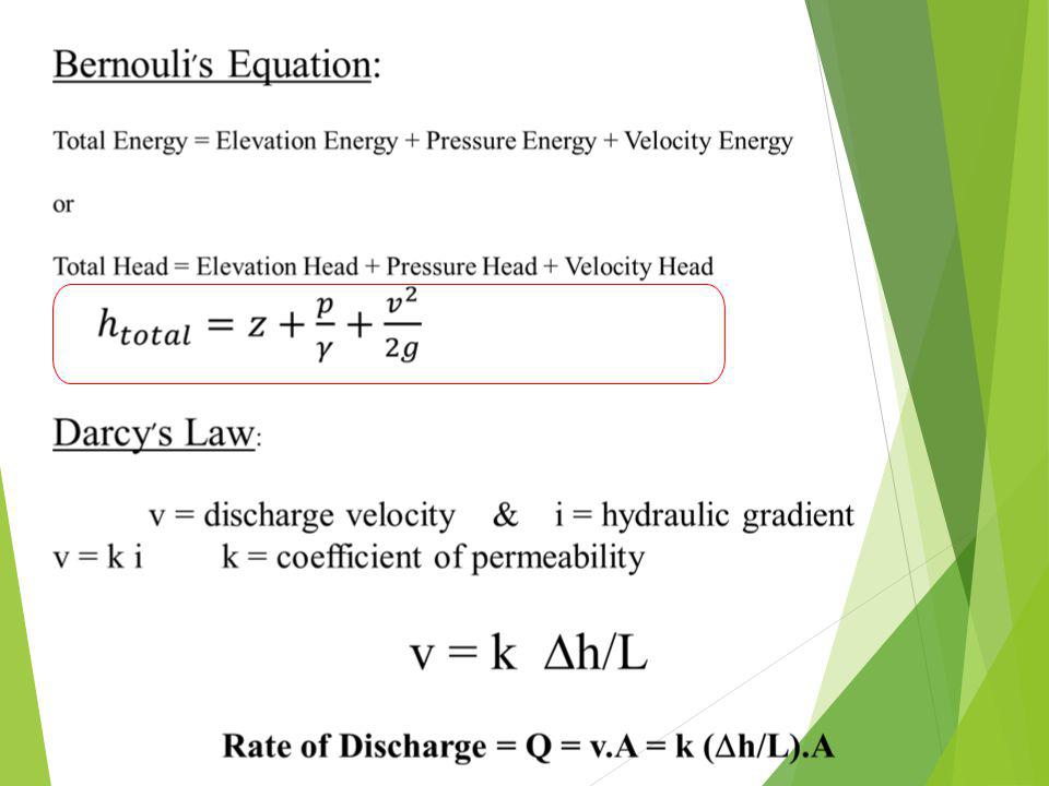
The fundamental description of permeability is based on the equation q=vA which takes the familiar form similar to river discharge. The variable q is the discharge (Vol/Time), v is the apparent velocity, and A is the area that is related to the geometry of the situation. Now, Darcy's Law describes the factors important in determining the value of v, which is v=ki where k is a constant for the material and is called the coefficient of permeability, and i is the hydraulic gradient which is related to the water pressure. The following table lists some soil permeabilities.

Presentasi serupa
 (1)>")


>")