Upload presentasi
Presentasi sedang didownload. Silahkan tunggu

1
Pengolahan Sinyal Digital

2
Perkembangan DSP Frequency Translate Digital Filter 512 Point FFT x(n)
X(f) Frequency Translate Digital Filter 1024 Point FFT X(f) Dedicated hardware signal processor Data Select Filter Select Data Select FFT Select Data Select Data Buffers Digital Filter Data Buffers FFT Data Buffers x(n) X(f) Micro programmable signal processor hardware
 Frequency. Translate. Digital. Filter Point. FFT. X(f) Dedicated hardware signal processor. Data Select. Filter Select. Data Select. FFT Select. Data Select. Data. Buffers. Digital. Filter. Data. Buffers. FFT. Data. Buffers. x(n) X(f) Micro programmable signal processor hardware.")
3
Programmable Signal Processor
Controller Data Storage x(n) Programmable S P Input/ Output X(f) Distributed Programmable Signal Processor Data Storage Data Storage x(n) Input/ Output X(f) Data Communication Controller x(n) Input/ Output X(f) Processing element Processing element
 Programmable. S P. Input/ Output. X(f) Distributed Programmable Signal Processor. Data. Storage. Data. Storage. x(n) Input/ Output. X(f) Data. Communication. Controller. x(n) Input/ Output. X(f) Processing. element. Processing. element.")
4
Perkembangan Processor
DSP 60an

5
Perkembangan Beaya (US$) 1970 1999
peningkatan 1 MHz Processing Power 7.601 0.17 x 1 Mbits storage 5.257 x Sending 1 TBits 0.12 x

6
What is DSP? Digital operating by the use of discrete signals to represent data in the form of numbers Signal a variable parameter by which information is conveyed through an electronic circuit Processing to perform operations on data according to programmed instructions Which leads us to a simple definition of: Digital Signal processing changing or analyzing information which is measured as discrete sequences of numbers

7
The advantages of DSP Versatility:
digital systems can be reprogrammed for other applications (at least where programmable DSP chips are used) digital systems can be ported to different hardware (for example a different DSP chip or board level product) Repeatability: digital systems can be easily duplicated digital systems do not depend on strict component tolerances digital system responses do not drift with temperature Simplicity: some things can be done more easily digitally than with analogue systems
 digital systems can be ported to different hardware (for example a different DSP chip or board level product) Repeatability: digital systems can be easily duplicated. digital systems do not depend on strict component tolerances. digital system responses do not drift with temperature. Simplicity: some things can be done more easily digitally than with analogue systems.")
8
Converting analogue signals to digital

9
In the process of measuring the signal, some information is lost.

10
Alising

11
The high frequency signal is sampled just under twice every cycle

12
The high frequency signal is sampled twice every cycle

13
Antialising

14
The Impulse respons of the reconstruction filter has a clasic :
sin (x)/ x shape
/ x shape.")
15
Frequency resolution

16
Quantisation

17
An analogue signal which is held on the rising edge of a clock signal

18
A real DSP system suffers from three sources of error due to limited word length in the measurement and processing of the signal: limited precision due to word length when the analogue signal is converted to digital form errors in arithmetic due to limited precision within the processor itself limited precision due to word length when the digital samples are converted back to analogue form These errors are often called 'quantization error'

19
Block Diagram

20
Spectrum

21
Digital signal Processing
Sistematika Disain DSP Analisis Diskrit Transformasi Z Finite Regst DSP Linier Sistem Diskrit Infinite Impulse Respons Digital Filter Finite Impulse Respons Digital Filter Multirate DSP FFT DFT Adaptive Filter Disain Digital signal Processing

22
Methodology System Design
Step 1 User/customer driven Develop system level Signal processing Non signal processing System level documentation Requirement specification Interface design specification System Requirements Defiition Step 2 Signal Analysis Step 3 Define input signal Types Parameter Noise sources & distribution Data rates Sisgnal Processing Design Step 4 Resource Analysis Dev SP graphs for each procss Specify primitive operation Initial partitioning Arithmetic analysis Iterative process Results in architecture approach Acceptable No Yes Step 5 Configuration Analysis Final partitioning of process Memory, Control, bandwidth Acceptable Perform resource analysis Configuration HW No Yes

23
HDTV - Jepang

24
Infinite Impulse Response (IIR)
Disain prosedure: Menggunakan formula disain untuk analog yaitu penentuan pole dan zero pada Butterworth, Chebyshev dan Elliptic Formula transformasi bidang frekuensi Transformasi bilinier, dg pemetaan pole pada bidang-s ke pole bidang-z

25
LPF Digital dan Analog

26
HPF LPF BSF BPF

27
Keuntungan Digital Filter
Stabil thd Panas: Perubahan temperatur pada R,C dan L tidak terjadi, karena menggunakan Adders, multipliers, dan sift registers Presisi: akurasi, stabilitas, respons frekw.dg menggunakan processor register. Mudah Penyesuaian: dapat lebih tepat dan dapat diprogram sesuai kebutuhan Kelipatan: dapat dilipatkan untuk mendapatkan rangkaian yang lebih efisien.

28
Kerugian Digital Filter
Bandwidth terbatas: dengan hasil proses sampling dari analog ke digital (A/D converter), bandwidth signal terbatas setengah dari frekuensi sampling. Keterbatasan register: implementasi sistem waktu diskrit pada perangkat keras dengan penggunaan khusus terjadi penurunan performance, karena terbatasnya jumlah bit.
, bandwidth signal terbatas setengah dari frekuensi sampling. Keterbatasan register: implementasi sistem waktu diskrit pada perangkat keras dengan penggunaan khusus terjadi penurunan performance, karena terbatasnya jumlah bit.")
29
Sistem Waktu Diskrit

30
Fungsi Transfer orde-N
Inverse Z-tranforms

31
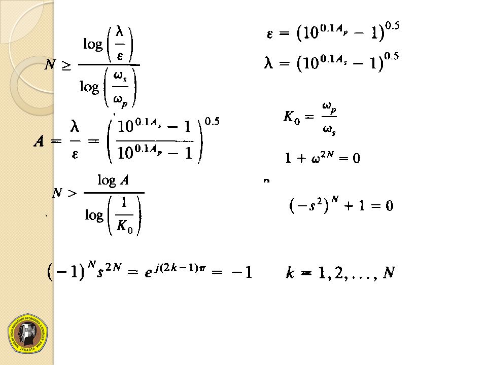
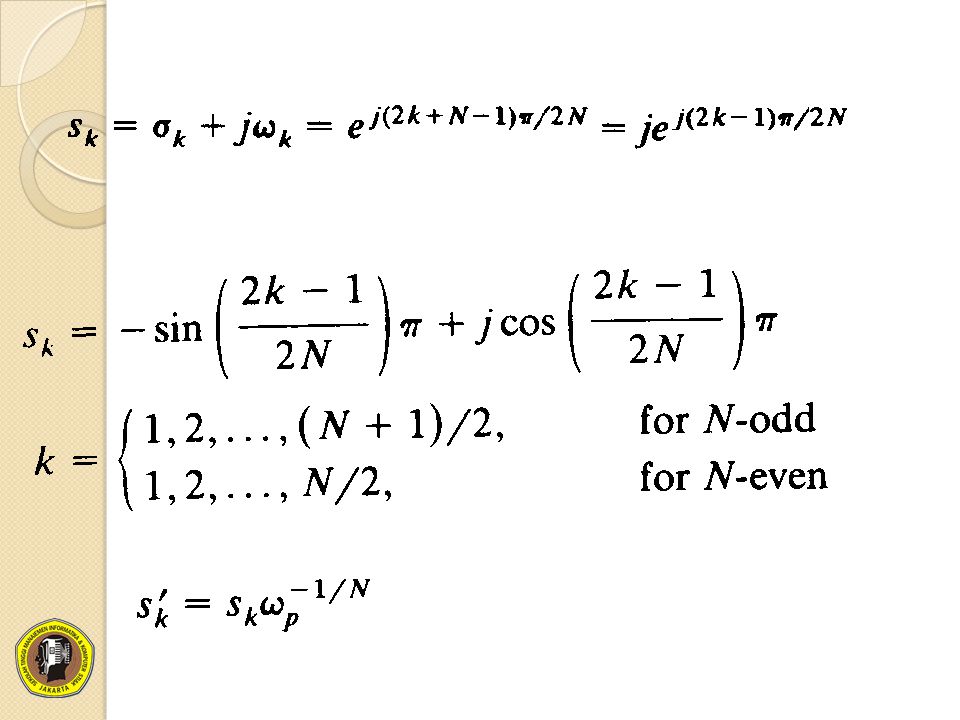
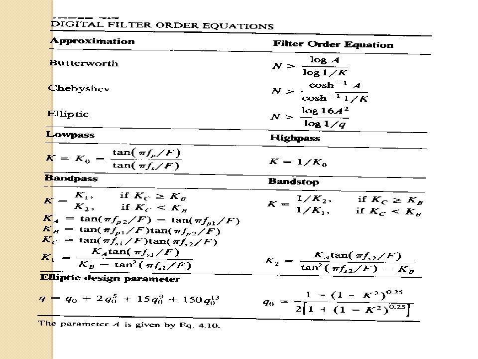
Lowpass Butterworth Filters

32
Respons Frekuensi

35
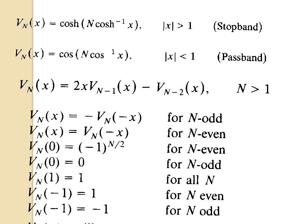
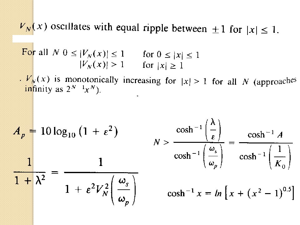
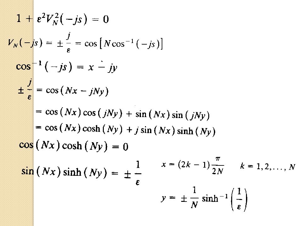
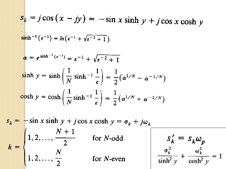
Analog Lowpass Chebyshev Filter

40
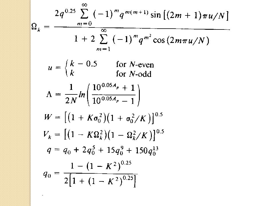
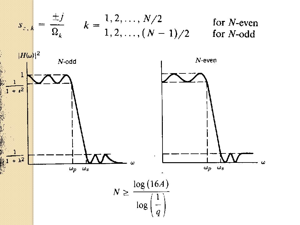
Analog Lowpass Elliptic Filter

43
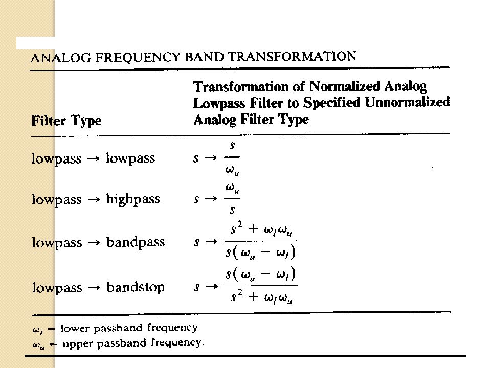
Transformasi Band Frekuensi
Design normalized analog filter of order N Perform Freq. Band Transformation analog to analog Desired Digital Filter Digitize filter Design normalized analog filter of order N Perform Freq. Band Transformation analog to analog Desired Digital Filter Digitize filter

45
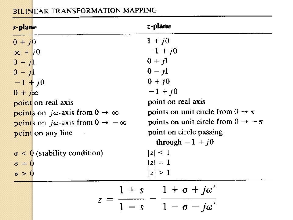
Transformasi Bilinier

47
Pemetaan Frekuensi dari transformasi bilinier

48
Digital Lowpass Filter Disain

51
Lowpass transfer function

52
LPF First order

55
Butterworth Low Pass Filter
fp = 500 Hz fs = 750 Hz Ap = dB As = 40 dB Ap As fp fs

56
S-plane Pole dan Zero Z-plane Pole dan Zero Zero Pole
No. Real Imaginary Real Imaginary Z-plane Pole dan Zero Zero Pole No. Real Imaginary Real Imaginary

57
Koefisien orde 2 Numerator Denominator
Stage A A B B2 IIR NORMALIZING FACTOR : C0 = STAGE 1 NORMALIZING FACTOR: C1 = STAGE 2 NORMALIZING FACTOR: C2 = STAGE 3 NORMALIZING FACTOR: C3 = STAGE 4 NORMALIZING FACTOR: C4 = STAGE 5 NORMALIZING FACTOR: C5 =

58
Frequency Response

59
Buku Referensi Digital Signal Processing A System Design Approach By: David J Defatta Josepth G Lucas William S Hodkins Digital Signal Processing Principles, Algorithms & Application By: John G Proakis Dimitris G Monolokis

60
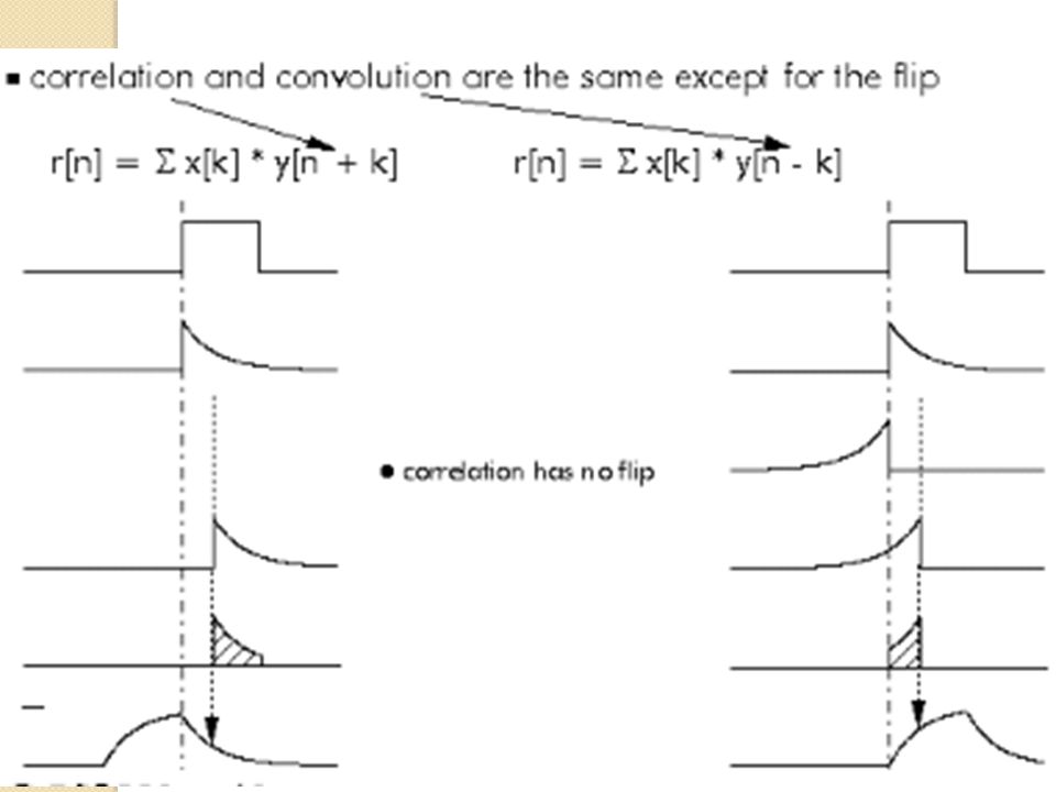
Correlation

61
Correlation is a maximum when two signals are similar in shape, and are in phase (or 'unshifted' with respect to each other).
.")
62
Three different types of signal

63
Autocorrelation

64
Cross correlation to identify a signal

65
Convolution

67
If one signal is symmetric, convolution and correlation are identical

68
Fourier Transforms

69
FIR

70
FIR design by the window

71
IIR

72
The Z Transform

73
Poles and Zeroes

74
TERIMA KASIH

Presentasi serupa

>")


>")


 CALIFORNIA MANAGEMENT REVIEW, 44 (4) 1seri.>")