Upload presentasi
Presentasi sedang didownload. Silahkan tunggu

1
KONSEP TEKNOLOGI PENGELOLAAN PENCEMARAN UDARA Oleh Sudrajat - FMIPA UNMUL - PROGRAM Magister Ilmu Lingkungan UNMUL 2005

2
Electrostatic Precipitators (ESPs)/ Pengendap Elektrostatik Alat pengendap elektrostatik digunakan untuk membersihkan udara yang kotor dalam jumlah yang relatif besar dan pengotor udaranya adalah aerosol atau uap air. Alat ini dapat membersihkan udara secara cepat dan udara yang keluar dari alat ini sudah relatif bersih. Alat pengendap ini menggunakan arus searah ( DC) yang mempunyai tegangan antara 25-100 kv. Alat pengendap ini berupa tabung silinder dimana dindingnya diberi muata positf, sedangkan di tengah ada sebuah kawat yang merupakan pusat silinder, sejajar dinding tabung, diberi muatan negatif. Adanya perbedaan yang cukup besar akan menimbulkan corona discharge di daerah sekitar pusat silinder. Hal ini menyebabkan seolah-olah udara kotor mengalami ionisasi.
 yang mempunyai tegangan antara kv. Alat pengendap ini berupa tabung silinder dimana dindingnya diberi muata positf, sedangkan di tengah ada sebuah kawat yang merupakan pusat silinder, sejajar dinding tabung, diberi muatan negatif. Adanya perbedaan yang cukup besar akan menimbulkan corona discharge di daerah sekitar pusat silinder. Hal ini menyebabkan seolah-olah udara kotor mengalami ionisasi..")
3
Kotoran udara menjadi ion negatif, sedangkan udara bersih menjadi ion positip dan masing-masing akan menuju elektroda yang sesuai. Kotoran yang menjadi ion negatif akan ditarik oleh dinding tabung, sedangkan udara bersih akan berada di tengah-tengah silinder dan kemudan terhembus ke luar.

4
Presipitator Elektrostatik Digunakan untuk membersihkan udara kotor dalam jumlah yg banyak dan jenis polutannya berupa aerosol atau uap air. Alat ini menggunakan arus searah ( DC) dengan tegangan antara 25 – 100 kv. Alat ini berbentuk tabung silinder dimana ddgnya diberi muatan +, sedangkan di tengah-tengahnya ada sebuah kawat yg merupakan pusat silinder, sejajar ddg tabung diberi muatan -. Adanya perbedaan tegangan ini akan menimbulkan muatan listrik di sekitar pusat silinder shg udara kotor mengalami ionisasi.
 dengan tegangan antara 25 – 100 kv. Alat ini berbentuk tabung silinder dimana ddgnya diberi muatan +, sedangkan di tengah-tengahnya ada sebuah kawat yg merupakan pusat silinder, sejajar ddg tabung diberi muatan -. Adanya perbedaan tegangan ini akan menimbulkan muatan listrik di sekitar pusat silinder shg udara kotor mengalami ionisasi..")
5
Figure: Electrostatic precipitator components

6
Dulu dapur silikon dan batubara serbuk menggunakan presipitator elektrostatik yang besar untuk menghilangkan partikel dari gas. Presipitator elektrostatik banyak digunakan untuk industri pembangkit daya dan mempunyai efisiensi koleksi sampai 99 %, tetapi tidak dapat berfungsi baik jika debu terbangnya ( flyash) memiliki tahanan listrik yg tinggi.
 memiliki tahanan listrik yg tinggi..")
7
Figure: Fabric filter (baghouse) components
 components")
8
Source Control Technology Control of gaseous pollutants from stationary sources Incineration Incineration, also known as combustion, is most used to control the emissions of organic compounds from process industries. This control technique refers to the rapid oxidation of a substance through the combination of oxygen with a combustible material in the presence of heat. When combustion is complete, the gaseous stream is converted to carbon dioxide and water vapor. Incomplete combustion will result in some pollutants being released into the atmosphere. Smoke is one indication of incomplete combustion.

9
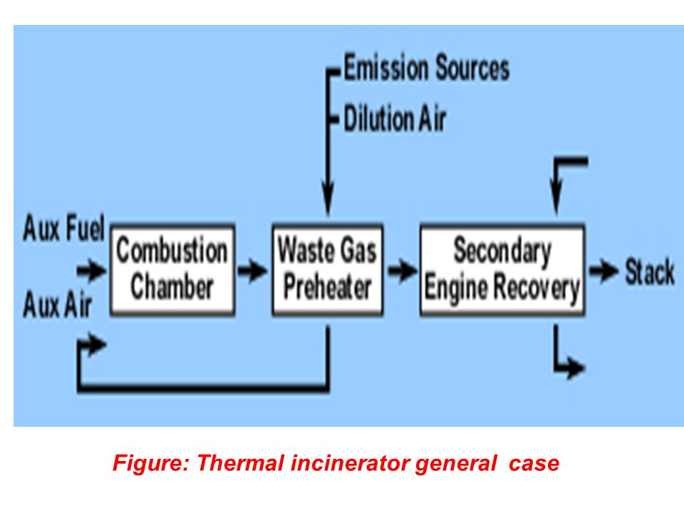
Equipment used to control waste gases by combustion can be divided in three categories: direct combustion or flaring, thermal incineration and catalytic incineration. Choosing the proper device depends on many factors, including type of hazardous contaminants in the waste stream, concentration of combustibles in the stream, process flow rate, control requirements, and an economic evaluation. A direct combustor or flare is a device in which air and all the combustible waste gases react at the burner. Complete combustion must occur instantaneously since there is no residence chamber. Flares are commonly used for disposal of waste gases during process upsets, such as those that take place when a process is started or shut down. A flare can be used to control almost any emission stream containing volatile organic compounds. Studies conducted by EPA have shown that the destruction efficiency of a flare is about 98 percent. Figure: Thermal incinerator general case

11
In thermal incinerators the combustible waste gases pass over or around a burner flame into a residence chamber where oxidation of the waste gases is completed. For thermal incineration, it is important that the vapor stream directed to the thermal incinerator have a constant combustible gas concentration and flow rate. These devices are not well-suited to vapor streams that fluctuate, because the efficiency of the combustion process depends on the proper mixing of vapors and a specific residence time in the combustion chamber. Residence time is the amount of time the fuel mixture remains in the combustion chamber. Often, supplementary fuel is added to a thermal incinerator to supplement the quantity of pollutant gases being burned by the incinerator. Energy and heat produced by the incineration process can be recovered and put to beneficial uses at a facility. Thermal incinerators can destroy gaseous pollutants at efficiencies of greater than 99 percent when operated correctly.

12
Figure: Catalytic incinerator

Presentasi serupa


>")

>")
 736711, Website:>")


>")
 (Part 2)>")

>")


