Upload presentasi
Presentasi sedang didownload. Silahkan tunggu

1
By : Prof. Dr. Tien R. Muchtadi
MEMBRANE TECHNOLOGY By : Prof. Dr. Tien R. Muchtadi

2
DEFINITIONS INTRODUCTION CLASSIFICATION OF MEMBRANE PROCESS
TYPES OF MEMBRANE REJECTION COEFFICIENT NOMINAL MW CUT-OFF GENERAL MEMBRANE EQUATION

3
INTRODUCTIONS Effective product separation is crucial to economic operation in process industries However, certain types of materials are inherently difficult and expensive to separate Prominent examples include : Finely dispersed solids, especially those which are compressible, have a density close to that of the liquid phase, have high viscosity, or are gelatinous Low molecular weight, non-volatile organics or pharmaceuticals and dissolved salts Biological materials which are very sensitive to their physical and chemical environment

4
A membrane may be defined as “an interphase separating two phases and selectively controlling the transport of materials between those phases Since 1960s a new technology using synthetics membrane for process separations has been rapidly developed by materials scientist, physical chemist and chemical engineers Such membrane separations have been widely applied to a range of conventionally difficult separation

5
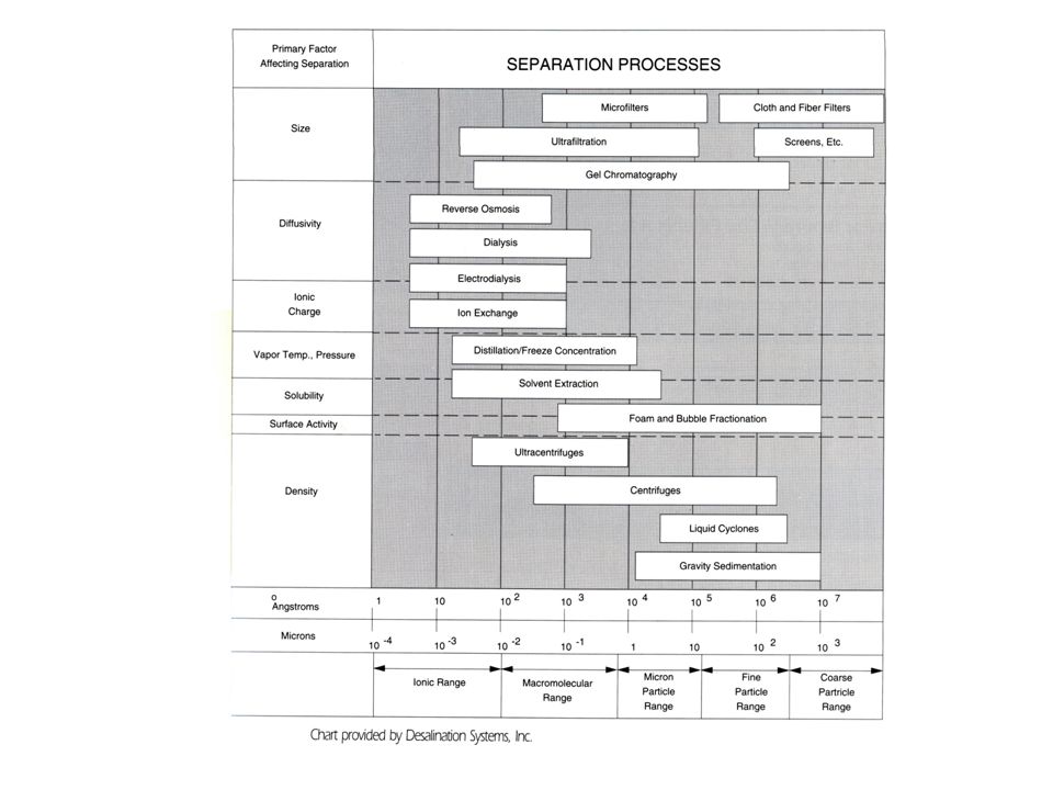
CLASSIFICATION OF MEMBRANE PROCESSES
Industrial membrane process may be classified according to the size range of materials which they are to separate and the driving force used in separations. There is always a degree of arbitrariness about such classification and the distinction which are typically drawn are shown in Table. 1

6
Table 1. Classifocation of membrane separation process for liquid systems
Name of process Driving force Separation size range Examples of materials separated Microfiltration Pressure gradient 10 – 0.1µm Small particles, large colloids,microbial cells Ultrafiltration < 0.1 µm – 5 nm Emulsions, colloids, macromolecules, proteins Reverse osmosis (hyperfiltration) < 5 nm Dissolved salts, small organics Electrodialysis Electric field gradient Dissolved salts Dialysis Concentration gradient Treatment of renal failure
 < 5 nm. Dissolved salts, small organics. Electrodialysis. Electric field gradient. Dissolved salts. Dialysis. Concentration gradient. Treatment of renal failure.")
7
THE NATURE OF SYNTHETIC MEMBRANES
Membrane used for separation process are most commonly made of polymeric materials Membrane have most commonly been produced by a form of phase inversion known as immersion precipitation This process has four main steps : The polymer is dissolved in a solvent to per cent by weight The resulting solution is cast on suitable support as film of thickness ~ 100 µm The film is quenched by immersion in non-solvent bath, typically water or an aqueous solution The resulting membrane is annealed by heating

8
GENERAL MEMBRANE EQUATION
The general membrane equation is an attempt to state the factor which may be important in determining the membrane permeation rate for pressure driven processes Form : J = |Δ P| - |ΔΠ| (Rm + Rc + Rf‘)µ
µ.")
9
J : the membrane permeation rate (flux expressed as volumetric rate per unit area)
Δ P : the pressure difference applied across the membrane (trans membrane pressure) ΔΠ : the difference in osmotic pressure across the membrane Rm : the resistance of the membrane Rc : the resistance of the layers depasited on the membrane (filter cake, gel foulants) Rf‘ : the resistance of the film layer
 ΔΠ : the difference in osmotic pressure across the membrane. Rm : the resistance of the membrane. Rc : the resistance of the layers depasited on the membrane (filter cake, gel foulants) Rf‘ : the resistance of the film layer.")
10
If the membrane is only exposed to pure solvent, exp water the equation become :
J = |ΔP|/Rmµ For microfiltration and ultrafiltration membranes where solvent flow is most often essentially laminar through an arrangement of tortous channels, this is analogous to the Carman-Kozeny equation Knowledge of such as water fluxes is useful for characterising new membrane and also for assesing the efectiveness of membrane cleaning procedures

11
MEMBRANE PROCESS MICROFILTRATION ULTRAFILTRATION (U/F)
REVERSE OSMOSIS (R/O) OR HYPERFILTRATION (H/F) MEMBRANE MODULES AND CONFIGURATIONS MEMBRANE FOULING, FLUX RATE REDUCTION, CLEANING AND PROCESS ECONOMICS
 OR HYPERFILTRATION (H/F) MEMBRANE MODULES AND CONFIGURATIONS. MEMBRANE FOULING, FLUX RATE REDUCTION, CLEANING AND PROCESS ECONOMICS.")
12
MICROFILTRATION Such filters use filter cloths as the filtration medium and are limited to concentrating particles above 5 µm in size Dead end membrane microfiltration, in which the particle containing fluid is pumped directly through a polymeric membrane, is used for industrial clarification and sterilization of liquids

13
The advantage of cross-flow filtration over conventional filtration are :
A higher overall liquid removal rate is achieved by prevention of the formation of an extensive filter cake The process feed remains in the form of mobile slurry suitable for further processing The solids content of the product slurry may be varied over a wide range It may be possible to fractionate particles of different sizes

14
Membrane Permeate Processing feed crossflow Retentate Permeate Figure 1. The Concept of Cross-Flow Filtration

15
Figure 2. Flow diagram for a simple cross-flow system

16
Membrane permeation rate
C b a Time Membrane permeation rate Figure 3. The time-dependence of membrane permeation rate duringcross-flow filtration : a. low cross-flow velocuty, b. increased cross-flow velocity, c. back-fushing at the bottom of each”saw-tooth”

17
MEMBRANE FOULING AND EFFECTS
FLUX RATE REDUCTION CLEANING METHODS PROCESS ECONOMICS : EFFECT OF FLUX RATE REDUCTION AND MEMBRANE LIFE ON OPERATING COSTS AND RETURN ON CAPITAL INVESMENT

18
ELECTRODIALYSIS OUTLINE OF MEMBRANE OPERATION
MEMBRANE TYPE AND TRANSPORT MECHANISM APPLICATIONS

19
LIQUID MEMBRANES TYPES OPERATING MECHANISM PRODUCT RECOVERY
APPLICATIONS

20
GAS SEPARATIONS MECHANISM TYPES OF MEMBRANE APPLICATIONS

21
CONCENTRATION OR GEL POLARISATION MODEL
APPLICATION OF THE DESIGN MODEL TO THE ULTRAFILTRATION CONCENTRATION AND SEPARATION OF GEL FORMING PROTEIN SOLUTION CALCULATIONS AND ASSUMPTIONS

22
APPLICATIONS OF MEMBRANE TECHNOLOGY
FOOD PROCESSING AND ENGINEERING BIOTECHNOLOGY, MEMBRANE REACTORS BIOMEDICAL ENGINEERING PROCESS DEVELOPMENT GROUP DISCUSSTION AND PROBLEM SOLVING

23
TEKNOLOGI SEPARASI MEMBRAN
Proses pemisahan komponen berdasarkan perbedaan berat dan ukuran molekul melalui suatu membran semipermeabel, dimana akan diperoleh komponen dengan ukuran molekul besar akan tertahan (retentate) dan komponen yang melewati membran (permeate)
 dan komponen yang melewati membran (permeate)")
24
KLASIFIKASI PROSES MEMBRAN
Berdasarkan pada driving force yang digunakan : Mikrofiltrasi Ultrafiltrasi Reverse osmosis Elektrodialysis Dialysis Paling banyak digunakan untuk pengolahan produk pangan

26
What Is Reverse Osmosis?
Reverse osmosis, as form of water treatment, is a technology in its infancy. The first membrane was developed in In the years following, membrane technology has grown a great deal and will continue to grow in the future. In fact, some of the membranes that are currently in use may be obsolete in a very short time, in favor of some new membrane material that is more resistant to a particular fouling contaminant. The reverse osmosis membrane is used for various applications from precious metal reclamation, to chemical reclamation, food processing nuclear waste reclamation, laboratory water purification, and on and on. We will limit our discussion to water purification and its laboratory applications.

27
To fully understand the technology of reverse osmosis, you must first understand the concept of normal osmosis. Simply put, in normal osmosis, water flows from a less concentrated solution through a semi-permeable membrane to a more concentrated solution (see figure 1). Reverse osmosis utilizes pressure to reverse normal osmotic flow, thus in reverse osmosis water flows from a more concentrated solution across semipermeable membrane to a less concentrated solution (see figure 2).
. Reverse osmosis utilizes pressure to reverse normal osmotic flow, thus in reverse osmosis water flows from a more concentrated solution across semipermeable membrane to a less concentrated solution (see figure 2)..")
28
BAHAN BAKU MEMBRAN ULTRAFILTRASI
Polimer (misal Polisulfon, Poliacrilonitril) dan keramik (Zirconium oxide, Aluminium oxide) Untuk memperoleh struktur membran dgn karakteristik tertentu selain bahan baku tadi juga diperlukan campuran pelarut dan aditif
 dan keramik (Zirconium oxide, Aluminium oxide) Untuk memperoleh struktur membran dgn karakteristik tertentu selain bahan baku tadi juga diperlukan campuran pelarut dan aditif.")
29
Karakteristik membran ultrafiltrasi : nilai MWCO (Molecular Weight Cut Off)
MWCO batas toleransi berat molekul (BM) senyawa yang dapat dipisahkan oleh suatu membran MWCO 10, membran dapat menahan (reject) sebanyak 95% komponen-komponen dengan BM ≥ 10,000, sedangkan komponen-komponen dengan BM lebih rendah akan melewati membran
 senyawa yang dapat dipisahkan oleh suatu membran. MWCO 10,000 membran dapat menahan (reject) sebanyak 95% komponen-komponen dengan BM ≥ 10,000, sedangkan komponen-komponen dengan BM lebih rendah akan melewati membran.")
30
Tabel 1. Aplikasi Teknik Separasi Membran pada Pengolahan Produk Pangan
No Teknik Proses Tujuan Proses Pustaka 1 Mikrofiltrasi Penghilangan pektin pada sari buah apel Zakoer and Mc. Lelan (1993) 2 Ultrafiltrasi Pemurnian isolat protein kedelai Debra and Cheryan (1981) 3 Penyederhanaan proses produksi sari buah apel Thomas, et.al. (1986) 4 Pemisahan komponen kasein Woychik et.,al (1992) 5 Penurunan kandungan bakteri pada kecap Tien and Chiang (1992) 6 Ultrafiltrasi & reverse osmosis Pengembangan berbagai produk tepung protein dari kacang tanah Lawhon, et., al (1981)
 2. Ultrafiltrasi. Pemurnian isolat protein kedelai. Debra and Cheryan (1981) 3. Penyederhanaan proses produksi sari buah apel. Thomas, et.al. (1986) 4. Pemisahan komponen kasein. Woychik et.,al (1992) 5. Penurunan kandungan bakteri pada kecap. Tien and Chiang (1992) 6. Ultrafiltrasi & reverse osmosis. Pengembangan berbagai produk tepung protein dari kacang tanah. Lawhon, et., al (1981)")
31
CONTOH PERCOBAAN SEPARASI MEMBRAN
Tujuan percobaan : Melakukan pembuatan membran ultrafiltrasi dari polimer polisulfon Melakukan annealing untuk menghasilkan membran dengan karakteristik tertentu Melakukan pengujian kinerja membran yang diperoleh untuk memisahkan senyawa dekstran (Dx) (BM = 71400) dan polietilen glikol (PEG) (BM= 20000), dan Melakukan studi literatur apliaksi membran yang dihasilkan pada pengolahan pangan
 (BM = 71400) dan polietilen glikol (PEG) (BM= 20000), dan. Melakukan studi literatur apliaksi membran yang dihasilkan pada pengolahan pangan.")
32
BAHAN DAN ALAT Bahan : polimer polisulfon (PS), pelarut dimetyhl-acetamide (DMAC), aditif nourmal methyl pirolidon (NMP), dekstran (BM=71.400) dan polietilen glikol (BM= 20000) Alat : alat separasi membran, alat casting, water bath, HPLC waters dan detektor refraktometer
, pelarut dimetyhl-acetamide (DMAC), aditif nourmal methyl pirolidon (NMP), dekstran (BM=71.400) dan polietilen glikol (BM= 20000) Alat : alat separasi membran, alat casting, water bath, HPLC waters dan detektor refraktometer")
33
METODOLOGI PERCOBAAN Pembuatan membran (Gambar 4)
Pengujian karakteristik membran proses annealing proses separasi membran Pengujian selektifitas membran mengamati prosentase rejeksi komponen dekstran dan polietilen glikol

34
Gambar 4. Diagram Alir proses pembuatan membran
Polimer Pelarut Aditif Pencampuran Pendiaman/relaxing Casting Gambar 4. Diagram Alir proses pembuatan membran Penguapan Koagulasi Membran sheet

35
Rejeksi (%) = [ 1-Cp/Cf ] x 100 %
Prosentase rejeksi dihitung dengan rumus : Rejeksi (%) = [ 1-Cp/Cf ] x 100 % Dimana : Cp = konsentrasi solute pada permeate Cf = konsentrasi pada feed Penentuan konsentrasi solute pada feed dan permeate dilakukan dengan metode HPLC menggunakan eluen aquadest, dgn flow rate 0.8 ml/menit dan volume injeksi 200 ml
![Rejeksi (%) = [ 1-Cp/Cf ] x 100 %](http://slideplayer.info/slide/3653724/12/images/35/Rejeksi+%28%25%29+%3D+%5B+1-Cp%2FCf+%5D+x+100+%25.jpg "Prosentase rejeksi dihitung dengan rumus : Rejeksi (%) = [ 1-Cp/Cf ] x 100 % Dimana : Cp = konsentrasi solute pada permeate. Cf = konsentrasi pada feed. Penentuan konsentrasi solute pada feed dan permeate dilakukan dengan metode HPLC menggunakan eluen aquadest, dgn flow rate 0.8 ml/menit dan volume injeksi 200 ml.")
36
Gambar Alat separasi membran skala laboratorium
Keterangan : Beaker geals pyrex Tutup bagian atas Tutup bagian bawah Tutup pengatur tekanan Aliran tekanan Saluran bahan Pengaduk magnetis M. Modul membran ultrafiltrasi Saluran pengeluaran Disk Polietilen penyangga membran S. Pemanas/hot plate

37
HASIL DAN PEMBAHASAN Membran dari polisulfon, pelarut dimetil acetamide (DMAc) dan aditif normal methyl pirolidon (NMP) dengan rasio 22: 62,4:15,6 hanya cocok untuk memisahkan dekstran dan senyawa lain dengan BM > Dengan menghitung waktu annealing saat persen 95% didapatkan MWCO membran polisulfon dan waktu annealing sebesar 6 menit.
 dan aditif normal methyl pirolidon (NMP) dengan rasio 22: 62,4:15,6 hanya cocok untuk memisahkan dekstran dan senyawa lain dengan BM > Dengan menghitung waktu annealing saat persen 95% didapatkan MWCO membran polisulfon dan waktu annealing sebesar 6 menit.")
38
Annealing akan memperbesar daya rejection
Peningkatan daya rejection diduga akibat perendaman dalam air hangat selama proses annealing sehingga pori-pori membran lebih teratur dalam jarak dan ukurannya

39
Peak area pada permeate
Hasil analisis HPLC karakteristik membran campuran polisulfon, DMAc, dan NMP pada perbadingan 22 : 62,4 : 15,6 Jenis feed Lama proses annealing Peak area pada feed Peak area pada permeate % rejection 1, PEG, BM = 20000 Non annealing 5 menit 15 menit 73.96 86.03 87.01 2. Dx, BM = 71400 527375 52.90 90.85 96.87

40
Gambar 5. Hubungan antara waktu annealing dan % rejection membran polisulfon terhadap dekstran (BM = 71400)
.")
41
APLIKASI MEMBRAN PADA PENGOLAHAN PANGAN
Kelebihan metoda separasi membran : Mampu memisahkan secara sempurna suatu campuran yang terdiri dari komponen-komponen dengan berat molekul yang berbeda-beda Untuk memisahkan komponen bernilai ekonomis tinggi Kelemahan : Memerlukan biaya yang relatif tinggi dibandingkan dengan cara ekstrasi ataupun distilasi konvensional

42
Salah satu contoh komponen dgn nilai ekonomis tinggi adalah ENZIM
Enzim : komponen protein (makromolekul) dgn BM besar (104 – 109) Proses imobilisasi menggunakan membran untuk enzim dg BM > 71400 Proses imobilisasi secara fisik berarti membran akan bersifat tidak permeable bagi enzim sehinga enzim dapat didaur ulang maupun dipalikasikan untuk proses produksi secara kontinu (Gambar 6.)
 dgn BM besar (104 – 109) Proses imobilisasi menggunakan membran untuk enzim dg BM > Proses imobilisasi secara fisik berarti membran akan bersifat tidak permeable bagi enzim sehinga enzim dapat didaur ulang maupun dipalikasikan untuk proses produksi secara kontinu (Gambar 6.)")
43
Produk Substrat + enzim Substrat Enzim Membran Gambar 6. Prinsip separasi membran untuk imobilisasi enzim

44
Tabel 2. Aplikasi proses separasi membran untuk imobilisasi enzim secara fisik
Jenis proses Jenis enzim terimobilisasi Karakteristik membran Jenis retentat komponen Jenis permeat komponen Pustaka Produksi sirup glukosa Glukoamylase dari Baciluss lichenifor, mis : termamyl MWCO 5000 Oligosakarida Glucoamylase Sirup glukosa Sims and Cheryan (1992) Produksi hidrolisat protein Protease dari Aspergillus Oryzae MWCO 10 kDa -protein -protease Asam-asam amino Zhang et al. (1996) Hidrolisis laktosa β- galactocidase dari Aspergillus oryzae MWCO > 30000 -laktosa - β- galactocidase Glukosa, galaktosa Sheth et al. (1988)
 Produksi hidrolisat protein. Protease dari Aspergillus Oryzae. MWCO 10 kDa. -protein. -protease. Asam-asam amino. Zhang et al. (1996) Hidrolisis laktosa. β- galactocidase dari Aspergillus oryzae. MWCO > laktosa. - β- galactocidase. Glukosa, galaktosa. Sheth et al. (1988)")
45
Karakteristik membran untuk imobilisasi enzim tergantung pada :
Jenis enzim yang akan diimobilisasi Jenis substrat yang diharapkan akan tertahan (retentate) pada membran Produk yang diharapkan melewati (permeate) membran
 pada membran. Produk yang diharapkan melewati (permeate) membran.")
46
HASIL PERCOBAAN Enzim yang akan diimobilisasi dan retentate substrat memiliki berat molekul lebih dari 71400, dan Produk hasil reaksi enzimatis (permeate) memiliki berat molekul lebih kecil dari 71400
 memiliki berat molekul lebih kecil dari")
47
TERIMA KASIH

Presentasi serupa

>")


 Anything needed by an organism or group of organism. Something useful (but for humanity what is useful or useless can change because.>")
>")


 DARI PATI GANDUM” Disusun oleh : Kelompok : 5 Aprilia Dian.>")


>")


>")