Upload presentasi
Presentasi sedang didownload. Silahkan tunggu

1
TOGAF 9 Fundamental: 6. UML Introduction
Romi Satria Wahono

2
Romi Satria Wahono SD Sompok Semarang (1987) SMPN 8 Semarang (1990)
SMA Taruna Nusantara Magelang (1993) B.Eng, M.Eng and Dr.Eng (on-leave) Department of Computer Science Saitama University, Japan ( ) Research Interests: Software Engineering and Intelligent Systems Founder IlmuKomputer.Com LIPI Researcher ( ) Founder and CEO PT Brainmatics Cipta Informatika
 B.Eng, M.Eng and Dr.Eng (on-leave) Department of Computer Science Saitama University, Japan ( ) Research Interests: Software Engineering and Intelligent Systems. Founder IlmuKomputer.Com. LIPI Researcher ( ) Founder and CEO PT Brainmatics Cipta Informatika.")
3
Course Outline Introduction Basic Concepts Core Concepts
Key Terminology ADM Introduction UML Introduction TOGAF Case Study

4
6. UML Introduction

5
The Nature of Software Development

6
Object-Oriented Programming

7
Is it Possible? romi@romisatriawahono.net Object-Oriented Programming

8
Systems Analysis and Design with UML

9
System Analysis and Design with UML
Business Process Identification Use Case Diagram Business Process Modeling Activity Diagram or Business Process Modeling Notation (BPMN) Business Process Realization Sequence Diagram (Buat untuk setiap use case dengan menggunakan pola Boundary-Control-Entity) System Design Program Design Class Diagram (Gabungkan Boundary-Control-Entity Class dan susun story dari sistem yang dibangun) Package Diagram (Gabungan class yang sesuai, boleh menggunakan pola B-C-E) Deployment Diagram (arsitektur software dari sistem yang dibangun) User Interface Design (Buat UI design dari Boundary Class) Entity-Relationship Model (Buat ER diagram dari Entity Class)
 Business Process Realization. Sequence Diagram (Buat untuk setiap use case dengan menggunakan pola Boundary-Control-Entity) System Design. Program Design. Class Diagram (Gabungkan Boundary-Control-Entity Class dan susun story dari sistem yang dibangun) Package Diagram (Gabungan class yang sesuai, boleh menggunakan pola B-C-E) Deployment Diagram (arsitektur software dari sistem yang dibangun) User Interface Design (Buat UI design dari Boundary Class) Entity-Relationship Model (Buat ER diagram dari Entity Class)")
10
1. Business Process Identification: Use Case Diagram

11
Use Case Diagrams Summarized into a single picture
All of the use cases for the part of the system being modeled Use case represents the discrete activities performed by the user Use Case Diagram tells what the system will do Good for communicating with users

12
Use Case Diagram Syntax
Actor person or system that derives benefit from and is external to the subject Use Case Represents a major piece of system functionality Association Relationship Include Relationship Extend Relationship Generalization Relationship <<includes>> <<extends>>

13
Use Case A major piece of system functionality
Can extend other Use Cases Placed inside system boundary Labeled with descriptive verb - noun phrase Use Case

14
System Boundary Boundary
Includes the name of the system inside or on top Represents the scope of the system Actors are outside the scope of the system Boundary

15
Actor A person or another system that interacts with the current system A role, not a specific user Provides input, receives output, or both actor Actor/Role

16
Association Relationship
Links actor and the Use Case Shows two-way communication If one-way, arrows are used * is for "multiplicity of the Association" * *

17
Extends Relationship Extends Use Case to include Optional behavior
Arrow points from the extension Use Case to the base Use Case extend extend Make Appointment Make Payment Arrangement

18
Include Relationship Include one Use Case from within another
Arrow points from base Use Case to the included Use Case include include Make New Patient Appointment Create New Patient

19
Generalization Relationship
A specialized Use Case to a more generalized Use Case Arrow points from specialized to general Use Case Make Old Appointment Make Appointment

20
Use Case Diagram for Appointment System

21
Use Case Diagram with Specialized Actor

22
Extend and Include Relationships

23
Studi Kasus: ATM System

24
ATM System

25
ATM System Layar Kotak Uang Kotak Kartu Kotak Kuitansi
Object-Oriented Programming ATM System Layar Kotak Uang Kotak Kartu Kotak Kuitansi

26
Masukkan PIN: Kotak Uang Kotak Kartu Kotak Kuitansi
Object-Oriented Programming Masukkan PIN: Kotak Uang Kotak Kartu Kotak Kuitansi

27
Menu Utama Melihat Saldo Mentransfer Uang Mengambil Uang Logout
Object-Oriented Programming Menu Utama Melihat Saldo Mentransfer Uang Mengambil Uang Logout Kotak Uang Kotak Kartu Kotak Kuitansi

28
Saldo anda adalah …. Menu Melihat Saldo Kotak Uang Kotak Kartu
Object-Oriented Programming Menu Melihat Saldo Saldo anda adalah …. Kotak Uang Kotak Kartu Kotak Kuitansi

29
No Account Penerima: Menu Mentransfer Uang Kotak Uang Kotak Kartu
Object-Oriented Programming Menu Mentransfer Uang No Account Penerima: Kotak Uang Kotak Kartu Kotak Kuitansi

30
Jumlah uang yang dikirim:
Object-Oriented Programming Menu Mentransfer Uang Jumlah uang yang dikirim: Kotak Uang Kotak Kartu Kotak Kuitansi

31
Uang berhasil terkirim
Object-Oriented Programming Menu Mentransfer Uang Uang berhasil terkirim Kotak Uang Kotak Kartu Kotak Kuitansi

32
Jumlah uang yang diambil:
Object-Oriented Programming Menu Mengambil Uang Jumlah uang yang diambil: Kotak Uang Kotak Kartu Kotak Kuitansi

33
Uang berhasil diambil Menu Mengambil Uang Kotak Uang Kotak Kartu
Object-Oriented Programming Menu Mengambil Uang Uang berhasil diambil Kotak Uang Kotak Kartu Kotak Kuitansi

34
Use Case Diagram

35
Use Case Diagram (Alternatif)
")
36
2. Business Process Modeling

37
System Analysis and Design with UML
Business Process Identification Use Case Diagram Business Process Modeling Activity Diagram or Business Process Modeling Notation (BPMN) Business Process Realization Sequence Diagram (Buat untuk setiap use case dengan menggunakan pola Boundary-Control-Entity) System Design Program Design Class Diagram (Gabungkan Boundary-Control-Entity Class dan susun story dari sistem yang dibangun) Package Diagram (Gabungan class yang sesuai, boleh menggunakan pola B-C-E) Deployment Diagram (arsitektur software dari sistem yang dibangun) User Interface Design (Buat UI design dari Boundary Class) Entity-Relationship Model (Buat ER diagram dari Entity Class)
 Business Process Realization. Sequence Diagram (Buat untuk setiap use case dengan menggunakan pola Boundary-Control-Entity) System Design. Program Design. Class Diagram (Gabungkan Boundary-Control-Entity Class dan susun story dari sistem yang dibangun) Package Diagram (Gabungan class yang sesuai, boleh menggunakan pola B-C-E) Deployment Diagram (arsitektur software dari sistem yang dibangun) User Interface Design (Buat UI design dari Boundary Class) Entity-Relationship Model (Buat ER diagram dari Entity Class)")
38
2.1 Business Process Modeling: Activity Diagram

39
BPM With Activity Diagrams
A number of activities support a business process across several departments Activity diagrams model the behavior in a business process

40
Actions and Activities
Performed for a specific business reason Names begin with a verb and end with a noun “Make Appointment” Each activity normally associated with a use case

41
Object Nodes Activity and Actions usually modify objects
Object nodes model these objects Objects represent a flow of information from between activities or actions

42
Control & Object Flows Control Flows (solid line)
Paths of execution through the business process Can only be attached to actions or activities Object Flows (dashed line) Model the flow of objects through a business process Show actual objects entering and exiting the system An object is on one end, an action or activity is on the other end
 Model the flow of objects through a business process. Show actual objects entering and exiting the system. An object is on one end, an action or activity is on the other end.")
43
Control Nodes Initial – Only one, at top left
Final Activity – Stop the process Final Flow – Stop this flow only Decision – Guarded test conditions Merge – Following decisions Fork – Split parallel execution Join – Join parallel execution

44
Swimlanes The business process may be broken into persons of responsibility Identify this with swimlanes

45
Activity Diagram Example

46
Creating Activity Diagrams
Set the context or scope of the activity being modeled Identify the activities and control/object flows between activities Identify any decisions made Look for opportunities for parallelism Draw the diagram

47
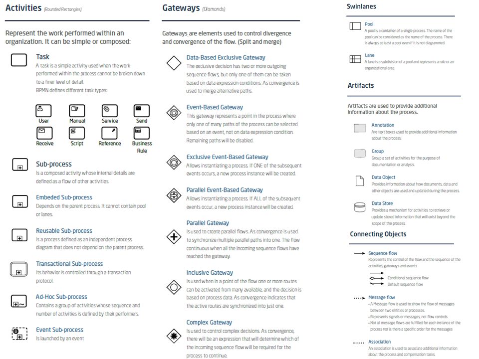
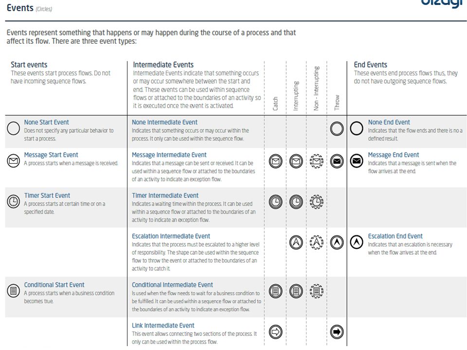
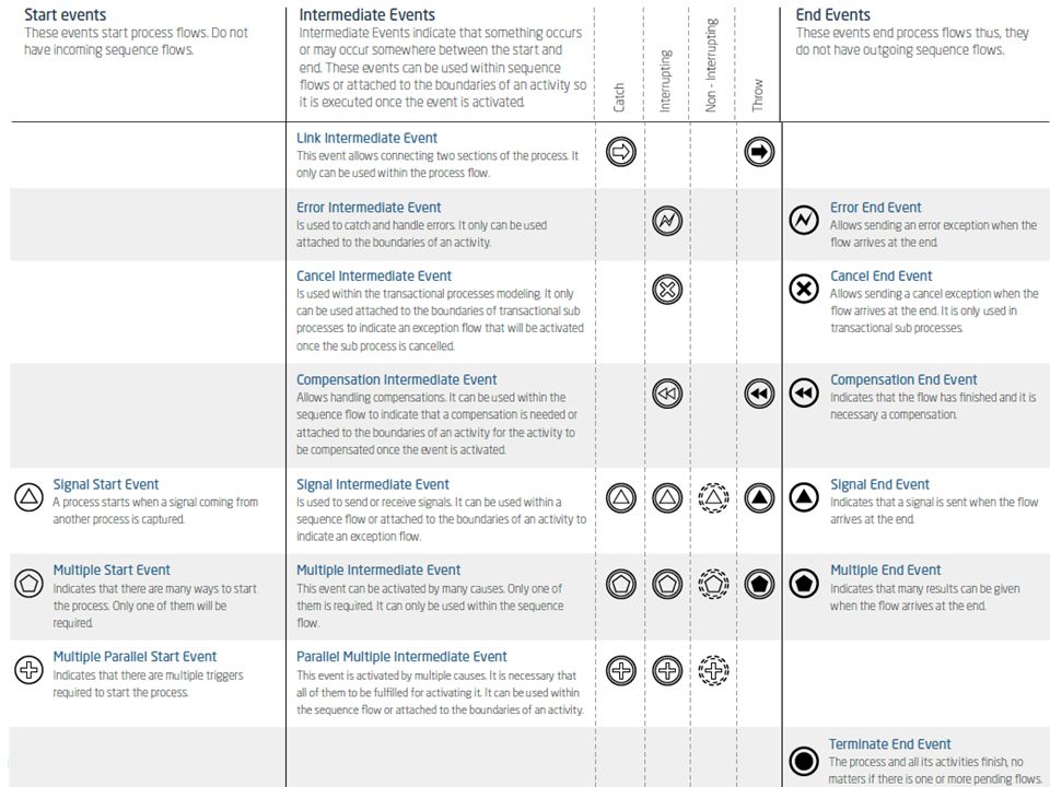
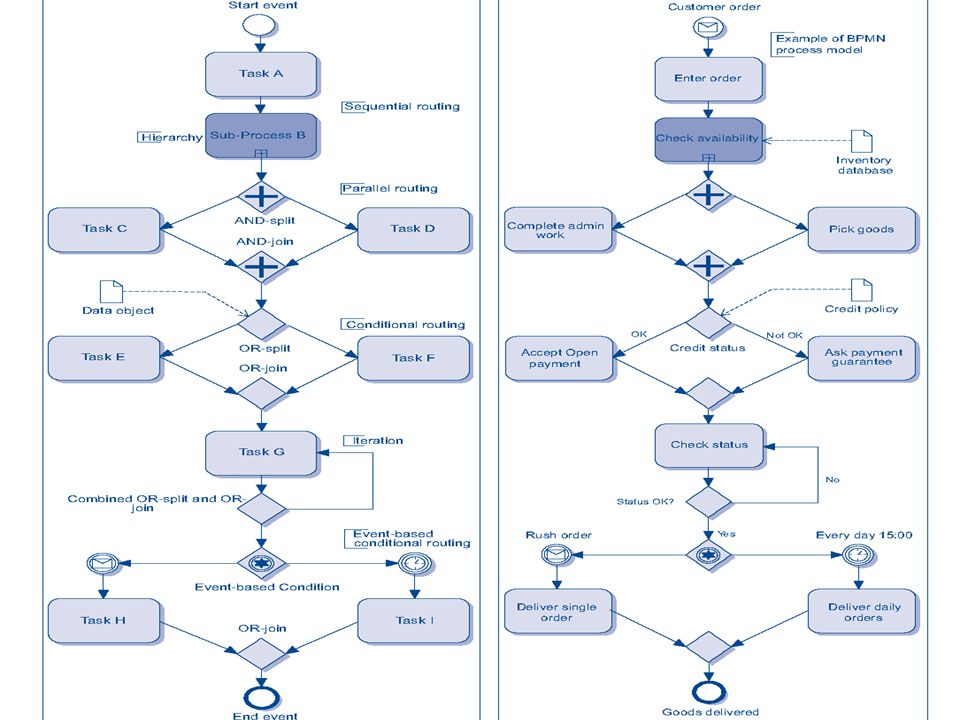
2.2 Business Process Modeling: Business Process Modeling Notation

52
Credit Application

53
Purchase Request

54
Shipment Process of a Hardware Retailer

55
The Pizza Collaboration

56
Order Fulfillment and Procurement

57
Studi Kasus: ATM System

58
Activity Diagram: Memasukkan Kartu

59
Activity Diagram: Memasukkan PIN

60
Activity Diagram: Mengecek Saldo

61
Activity Diagram: Mentransfer Uang

62
Activity Diagram: Mengambil Uang

63
Activity Diagram: Melakukan Logout

64
3. Business Process Realization: Sequence Diagram

65
System Analysis and Design with UML
Business Process Identification Use Case Diagram Business Process Modeling Activity Diagram or Business Process Modeling Notation (BPMN) Business Process Realization Sequence Diagram (Buat untuk setiap use case dengan menggunakan pola Boundary-Control-Entity) System Design Program Design Class Diagram (Gabungkan Boundary-Control-Entity Class dan susun story dari sistem yang dibangun) Package Diagram (Gabungan class yang sesuai, boleh menggunakan pola B-C-E) Deployment Diagram (arsitektur software dari sistem yang dibangun) User Interface Design (Buat UI design dari Boundary Class) Entity-Relationship Model (Buat ER diagram dari Entity Class)
 Business Process Realization. Sequence Diagram (Buat untuk setiap use case dengan menggunakan pola Boundary-Control-Entity) System Design. Program Design. Class Diagram (Gabungkan Boundary-Control-Entity Class dan susun story dari sistem yang dibangun) Package Diagram (Gabungan class yang sesuai, boleh menggunakan pola B-C-E) Deployment Diagram (arsitektur software dari sistem yang dibangun) User Interface Design (Buat UI design dari Boundary Class) Entity-Relationship Model (Buat ER diagram dari Entity Class)")
66
Sequence Diagrams Illustrate the objects that participate in a use case Show the messages that pass between objects for a particular use-case over time

67
Sequence Diagram Syntax
AN ACTOR AN OBJECT A LIFELINE A FOCUS OF CONTROL A MESSAGE OBJECT DESTRUCTION anObject:aClass aMessage() x
 x.")
68
Sequence Diagram Susun Sequence Diagram untuk setiap Use Case yang dibuat Mulai dari menarik Actor yang ada di Use Case Diagram, lanjutkan dengan membuat sequence detail dari berjalannya Use Case Catatan: Objek dari Lifeline di Sequence Diagram akan menjadi kandidat Class

69
Jenis Class Boundary Class: Control Class: Entity Class:
Class yang berinteraksi dengan aktor langsung (user interface) Form, input, UI ini masuk di sini Control Class: Class yang berhubungan dengan pemrosesan, penghitungan, kalkulasi, komputasi, query, dst Entity Class: Class yang berhubungan dengan data, penyimpanan data/file
 Form, input, UI ini masuk di sini. Control Class: Class yang berhubungan dengan pemrosesan, penghitungan, kalkulasi, komputasi, query, dst. Entity Class: Class yang berhubungan dengan data, penyimpanan data/file.")
70
Studi Kasus: ATM System

71
Sequence Diagram: Memasukkan Kartu

72
Sequence Diagram: Memasukkan PIN

73
Sequence Diagram: Mengecek Saldo

74
Sequence Diagram: Mentransfer Uang

75
Sequence Diagram: Mengambil Uang

76
Sequence Diagram: Melakukan Logout

77
Estimating Project Size with Use Case Points

78
Use Case Points Alternative to Function Point Approach
Classify actors and use cases as: Simple Average Complex (Gustav Karner, 1993)
")
79
Actor and Use Case Weighting Tables
Unadjusted Actor Weighting (UAW) Actor Type Description Weighting Factor Simple External System with well-defined API 1 Average External System using a protocol-based interface, e.g., HTTP, TCT/IP, SQL 2 Complex Human 3 Unadjusted Use Case Weighting (UUCW) Use-Case Type Description Weighting Factor Simple 1-3 transactions 5 Average 4-7 transactions 10 Complex More than 7 transactions 15 Unadjusted Use Case Points (UUCP) = UAW + UUCW
 Actor Type. Description. Weighting Factor. Simple. External System with well-defined API. 1. Average. External System using a protocol-based. interface, e.g., HTTP, TCT/IP, SQL. 2. Complex. Human. 3. Unadjusted Use Case Weighting (UUCW) Use-Case Type. Description. Weighting Factor. Simple. 1-3 transactions. 5. Average. 4-7 transactions. 10. Complex. More than 7 transactions. 15. Unadjusted Use Case Points (UUCP) = UAW + UUCW.")
80
Technical Complexity Factors
Factor Number Description Weight T1 Distributed system 2.0 T2 Response time or throughput performance objectives 1.0 T3 End-user online efficiency T4 Complex internal processing T5 Reusability of code T6 Easy to install 0.5 T7 Ease of use T8 Portability T9 Ease of change Technical Complexity Factor (TCF) = (0.01 * TFactor)
 = (0.01 * TFactor)")
81
Environmental Complexity Factors
Factor Number Description Weight E1 Familiarity with system development process in use 1.5 E2 Application experience 0.5 E3 Object-oriented experience 1.0 E4 Lead analyst capability E5 Motivation E6 Requirements stability 2.0 E7 Part time staff -1.0 E8 Difficulty of programming language Environmental Factor (EF) = (-0.03 * EFactor)
 = (-0.03 * EFactor)")
82
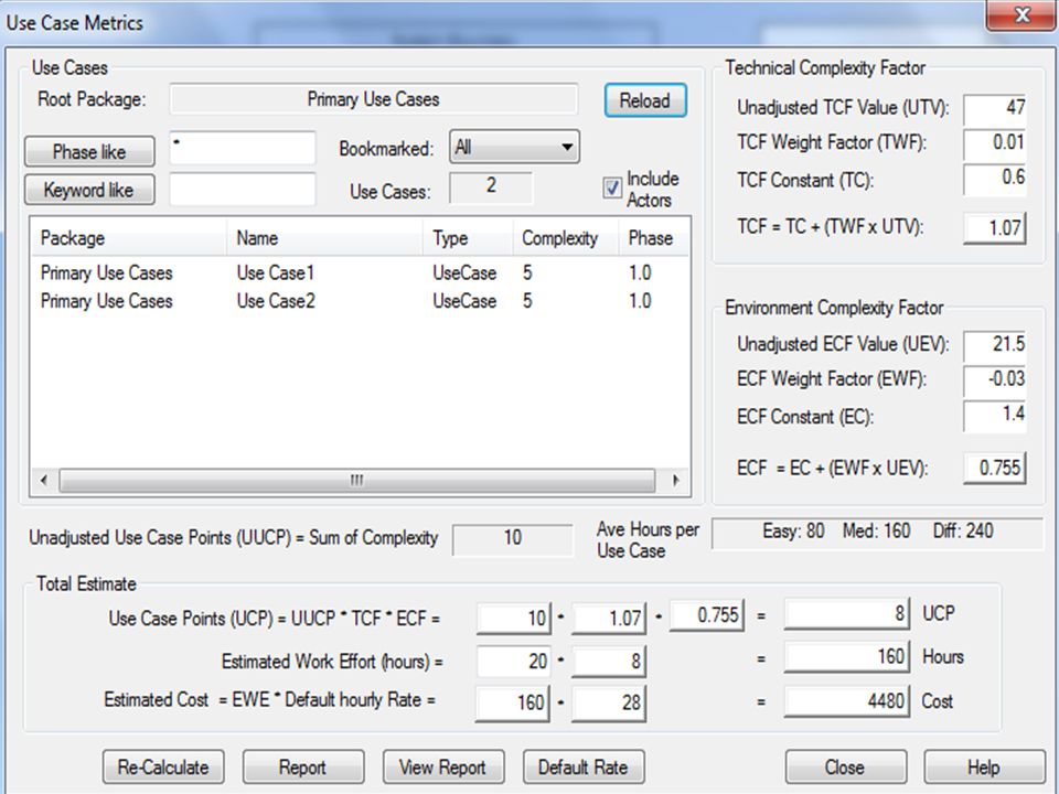
Computing Use Case Points
Adjusted Use Case Points (UCP) = UUCP * TCF * ECF Effort in Person Hours = UCP * PHM
 = UUCP * TCF * ECF. Effort in Person Hours = UCP * PHM.")
83
Person Hour Multiplier (PHM)
If the sum of (number of Efactors E1 through E6 assigned value < 3) and (number of Efactors E7 and E8 assigned value > 3) ≤ 2 PHM = 20 Else If the sum of (number of Efactors E1 through E6 assigned value < 3) and (number of Efactors E7 and E8 assigned value > 3) = 3 or 4 PHM 28 Else Rethink project; it has too high of a risk for failure
 and (number of Efactors E7 and E8 assigned value > 3) ≤ 2 PHM = 20 Else If the sum of (number of Efactors E1 through E6 assigned value < 3) and (number of Efactors E7 and E8 assigned value > 3) = 3 or 4 PHM 28 Else Rethink project; it has too high of a risk for failure")
84
Person Hour Multiplier (PHM)
Now it’s time to compute effort Let F1 = Number of E1 to E6 that are < 3 Let F2 = Number of E7 and E8 that are > 3 If F1 + F2 <= 2 PHM = 20 Else if F1 + F2 = 3 or 4 PHM = 28 Else Scrap the project

85
Person Month UCP = 42 PH = 20 * UCP = 20*42 = 840
PM = 840/8/22 = 4.7 (5 P/M)
")
86
Effort Estimation from PM Defined
PM = 840/8/22 = 4.7 P/M TIME = 3.0 * PM 1/3 TIME = 3.0 * 4.7 1/3 TIME = 3.0 * 1.68 TIME = 5 month

87
Effort Estimation from PM Defined
PM = 840/12/28 = 2.5 P/M TIME = 3.0 * PM 1/3 TIME = 3.0 * 2.5 1/3 TIME = 3.0 * 1.3 TIME = 4 month

88
Time

89
Use Case Points in EA

91
Effort Estimation from PM Defined
PM = 520/8/22 = 2.95 P/M TIME = 3.0 * PM 1/3 TIME = 3.0 * /3 TIME = 3.0 * 1.43 TIME = 4.3 month

92
Budget (Custom Software)
Pekerjaan Man-Month Month Budget Total Planning 1 Analysis 2 Design Implementation 4 Training

93
Budget (Generic Software)
Product Total LMS Teleconference Chatting eLibrary

94
4. Class Diagram

95
System Analysis and Design with UML
Business Process Identification Use Case Diagram Business Process Modeling Activity Diagram or Business Process Modeling Notation (BPMN) Business Process Realization Sequence Diagram (Buat untuk setiap use case dengan menggunakan pola Boundary-Control-Entity) System Design Program Design Class Diagram (Gabungkan Boundary-Control-Entity Class dan susun story dari sistem yang dibangun) Package Diagram (Gabungan class yang sesuai, boleh menggunakan pola B-C-E) Deployment Diagram (arsitektur software dari sistem yang dibangun) User Interface Design (Buat UI design dari Boundary Class) Entity-Relationship Model (Buat ER diagram dari Entity Class)
 Business Process Realization. Sequence Diagram (Buat untuk setiap use case dengan menggunakan pola Boundary-Control-Entity) System Design. Program Design. Class Diagram (Gabungkan Boundary-Control-Entity Class dan susun story dari sistem yang dibangun) Package Diagram (Gabungan class yang sesuai, boleh menggunakan pola B-C-E) Deployment Diagram (arsitektur software dari sistem yang dibangun) User Interface Design (Buat UI design dari Boundary Class) Entity-Relationship Model (Buat ER diagram dari Entity Class)")
96
Class Diagram Elements
Classes Attributes Operations Relationships

97
Classes Templates for creating instances or objects
All objects of a class have same structure and behavior, but contain different attributes Concrete: used to create actual objects Abstract: extended to create other classes

98
Attributes Units of information relevant to the description of the class Only attributes important to the task should be included Attributes should be primitive types (integers, strings, doubles, date, time, Boolean, etc.)
")
99
Operations (Methods) Defines the behavior of the class
Action that instances/objects can take Focus on relevant problem-specific operations (at this point)
")
100
Relationships Generalization Aggregation “Is-A” relationship
Enables inheritance of attributes & oper's Subclasses and superclasses Principle of substitutability Subclass be substituted for superclass Aggregation “Has-A” relationship Relates parts to wholes Uses decomposition

101
Relationships Association
Relationships that don't fit “Is-A” or “Has-A” Often a weaker form of “Has-A” Miscellaneous relationships between classes Example: Patient schedules an appointment So the appointment has a patient This is weak

102
Example Class Diagram

103
More on Attributes Derived attributes Visibility of attributes
/age, for example can be calculated from birth date and current date Visibility of attributes +Public: not hidden from any object #Protected: hidden from all but immediate subclasses –Private: hidden from all other classes Default is private

104
More on Operations Constructor: creates object Query: see class state
Update: change attribute values Operations can also be public, protected, or private Default for operations is public

105
More on Relationships A primary purpose of class diagrams is to show relationships, or associations, between classes Class can be related to itself (role) Use a "+" sign to show it's a role and not the name of a relationship
 Use a + sign to show it s a role and not the name of a relationship.")
106
Relationship Multiplicity
Exactly one Zero or more One or more Zero or one Specified range Disjoint ranges Dept Boss 1 Employee Child 0..* Boss Employee 1..* Employee Spouse 0..1 Employee Vacation 2..4 Employee Committee 1..3, 5

107
Class Diagram: Internet Order Project

108
Class Diagram: Sistem ATM

109
5. Deployment Diagram

110
System Analysis and Design with UML
Business Process Identification Use Case Diagram Business Process Modeling Activity Diagram or Business Process Modeling Notation (BPMN) Business Process Realization Sequence Diagram (Buat untuk setiap use case dengan menggunakan pola Boundary-Control-Entity) System Design Program Design Class Diagram (Gabungkan Boundary-Control-Entity Class dan susun story dari sistem yang dibangun) Package Diagram (Gabungan class yang sesuai, boleh menggunakan pola B-C-E) Deployment Diagram (arsitektur software dari sistem yang dibangun) User Interface Design (Buat UI design dari Boundary Class) Entity-Relationship Model (Buat ER diagram dari Entity Class)
 Business Process Realization. Sequence Diagram (Buat untuk setiap use case dengan menggunakan pola Boundary-Control-Entity) System Design. Program Design. Class Diagram (Gabungkan Boundary-Control-Entity Class dan susun story dari sistem yang dibangun) Package Diagram (Gabungan class yang sesuai, boleh menggunakan pola B-C-E) Deployment Diagram (arsitektur software dari sistem yang dibangun) User Interface Design (Buat UI design dari Boundary Class) Entity-Relationship Model (Buat ER diagram dari Entity Class)")
111
System Architectures Components
Servers Mainframes, Minis, Micros Clients Input/Output HW used by users Terminals, PCs, special purpose HW Network HW and SW to connect clients to servers

112
Deployment Diagram Components
Nodes Any piece of hardware in the model A computational resource Labeled by its name Stereotype to label the type of node Artifacts Piece of the information system Such as software or a database table

113
Deployment Diagram Components
Node with Deployed Artifact Shows artifact placed on a physical node Good for showing distribution data or software Communication paths Links between nodes of the network

114
Node with Deployment Artifact
Deployment Diagram Node Artifact Node with Deployment Artifact Communication Path

115
Deployment Diagram Examples

116
Deployment Diagram (2 Tier)
")
117
6. Data Model

118
System Analysis and Design with UML
Business Process Identification Use Case Diagram Business Process Modeling Activity Diagram or Business Process Modeling Notation (BPMN) Business Process Realization Sequence Diagram (Buat untuk setiap use case dengan menggunakan pola Boundary-Control-Entity) System Design Program Design Class Diagram (Gabungkan Boundary-Control-Entity Class dan susun story dari sistem yang dibangun) Package Diagram (Gabungan class yang sesuai, boleh menggunakan pola B-C-E) Deployment Diagram (arsitektur software dari sistem yang dibangun) User Interface Design (Buat UI design dari Boundary Class) Entity-Relationship Model (Buat ER diagram dari Entity Class)
 Business Process Realization. Sequence Diagram (Buat untuk setiap use case dengan menggunakan pola Boundary-Control-Entity) System Design. Program Design. Class Diagram (Gabungkan Boundary-Control-Entity Class dan susun story dari sistem yang dibangun) Package Diagram (Gabungan class yang sesuai, boleh menggunakan pola B-C-E) Deployment Diagram (arsitektur software dari sistem yang dibangun) User Interface Design (Buat UI design dari Boundary Class) Entity-Relationship Model (Buat ER diagram dari Entity Class)")
119
Data Model

120
References Rachel Harrison, Study Guide TOGAF® 9 Foundation 2nd Edition, The Open Group, 2011 Rachel Harrison, Study Guide TOGAF® 9 Certified 2nd Edition, The Open Group, 2011 Open Group Standard, TOGAF® Version 9.1 (G116), The Open Group, 2011 Open Group Standard, TOGAF® Version 9.1 – A Pocket Guide (G117), The Open Group, 2011 Daniel Minoli, Enterprise Architecture A to Z: Frameworks, Business Process Modeling, SOA, and Infrastructure Technology, Taylor & Francis, 2008 Jon Holt and Simon Perry, Modelling Enterprise Architectures, The Institution of Engineering and Technology, 2010 Alan Dennis et al, Systems Analysis and Design with UML 4th Edition, John Wiley and Sons, 2013
, The Open Group, Open Group Standard, TOGAF® Version 9.1 – A Pocket Guide (G117), The Open Group, Daniel Minoli, Enterprise Architecture A to Z: Frameworks, Business Process Modeling, SOA, and Infrastructure Technology, Taylor & Francis, Jon Holt and Simon Perry, Modelling Enterprise Architectures, The Institution of Engineering and Technology, Alan Dennis et al, Systems Analysis and Design with UML 4th Edition, John Wiley and Sons,")
Presentasi serupa
>")


>")


