Upload presentasi
Presentasi sedang didownload. Silahkan tunggu

1
Digital Logic Symbols For Logic gates
Gerbang OR identik dengan saklar parallel Gerbang AND identik dengan saklar seri

2
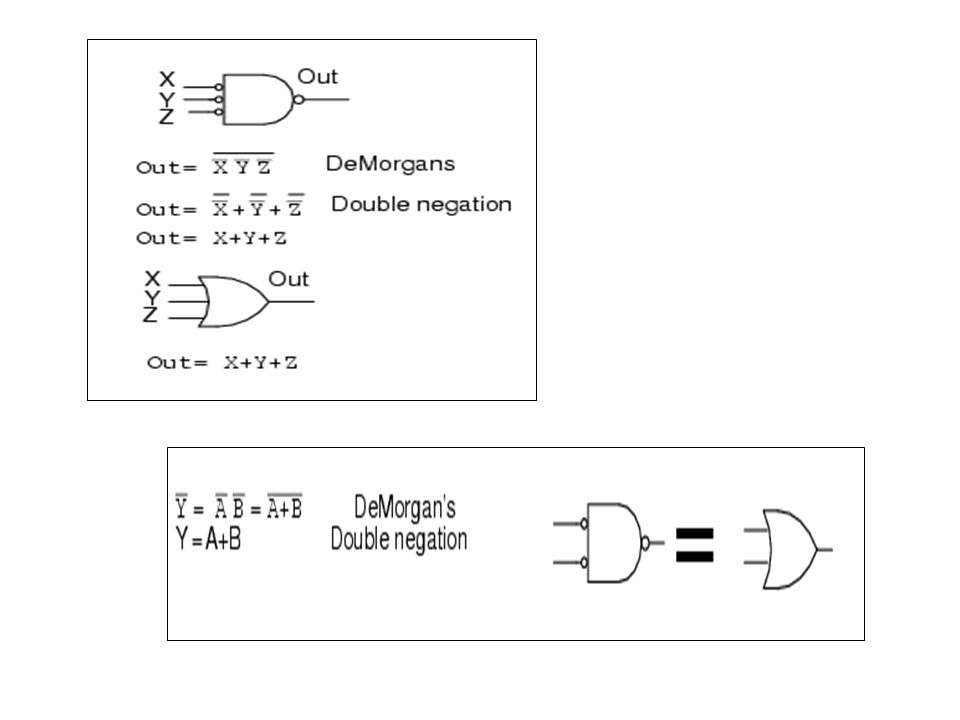
Digital Logic Symbols For Logic gates

3
Digital Logic Universal gates

4
Digital Logic Universal gates

5
Digital Logic Multiple Input gates

6
Digital Logic Multiple Input / output gates

8
Digital Circuits and Relationship to Boolean Algebra

9
CONTOH. Buatlah rangkaian dengan Gerbang Logika untuk aljabar Boolean sbb. X . ( X’ + Y ) Jawab. X X.( X’+Y) Y
 Y.")
10
Logic Diagrams and Expressions
Truth Table 1 1 1 1 1 1 0 1 0 1 1 0 0 0 1 1 0 1 0 0 0 1 0 0 0 X Y Z Z Y X F × + = Equation Z Y X F + = X Y F Z Logic Diagram Boolean equations, truth tables and logic diagrams describe the same function! Truth tables are unique; expressions and logic diagrams are not. This gives flexibility in implementing functions.

11
Contoh : Buatlah persamaan boolean dan rangkaian logika dari fungsi boolean dalam bentuk Minterm sbb F(ABC) = ( 0,3,6,7 )
 = ( 0,3,6,7 )")
12
= A’B’C’ + A’BC + ABC’ + ABC = A’(B’C’ + BC) + AB(C’ + C)
Persamaan Boolean F = Fi = F0 + F3 + F6 + F7 = A’B’C’ + A’BC + ABC’ + ABC = A’(B’C’ + BC) + AB(C’ + C) = A’(B C) + AB Rangkaian logika F(ABC) = A(B C) + AB A B C
 + AB(C’ + C) = A’(B C) + AB. Rangkaian logika. F(ABC) = A(B C) + AB. A. B. C.")
13
Tentukan output dari rangkaian logika dibawah !
Rangkaian yang mana outputnya dalam bentuk POS, atau SOP ?

14
Tentukan output dari rangkaian logika dibawah !
Apakah outputnya dalam bentuk POS, atau SOP ?

16
Buffer A buffer is a gate with the function F = X:
In terms of Boolean function, a buffer is the same as a connection! So why use it? A buffer is an electronic amplifier used to improve circuit voltage levels and increase the speed of circuit operation. X F

17
XOR/XNOR (Continued) Z Y X Å Å + + + = = Y Z ) ( X 1 Å = =
The XOR function can be extended to 3 or more variables. For more than 2 variables, it is called an odd function or modulo 2 sum (Mod 2 sum), not an XOR: The complement of the odd function is the even function. The XOR identities: Z Y X Å Å + + + = X 1 Å = Y Z ) ( = =
, not an XOR: The complement of the odd function is the even function. The XOR identities: Z. Y. X. Å. Å = X. 1. Å. = Y. Z. ) ( = =")
18
IC LOGIC

19
IC LOGIC

20
Gates

21
IC LOGIC Digital IC types SSI- few gates, basic logic operations
MSI gates, performs complete logic function LSI- more than 100 gates VLSI- thousands of gates

22
Expression Simplification
An application of Boolean algebra Simplify to contain the smallest number of literals (complemented and uncomplemented variables): = AB + ABCD + A C D + A C D + A B D = AB + AB(CD) + A C (D + D) + A B D = AB + A C + A B D = B(A + AD) +AC = B (A + D) + A C 5 literals + D C B A
: = AB + ABCD + A C D + A C D + A B D. = AB + AB(CD) + A C (D + D) + A B D. = AB + A C + A B D = B(A + AD) +AC. = B (A + D) + A C 5 literals. + D. C. B. A.")
23
Simplify the following boolean function to a minimum number of literals.
X+x’y=(x+x’)(x+y)=x+y X(x’+y)=xx’+xy=0+xy=xy X’y’z+x’yz+xy’=x’z(y’+y)+xy’=x’z+xy’ Xy+x’z+yz=xy+x’z+yz(x+x’) =xy+x’z+xyz+x’yz =xy(1+z)+x’z(1+y) =xy+x’z 5. (x+y)(x’+z)(y+z)=(x+y)(x’+z)
(x+y)=x+y. X(x’+y)=xx’+xy=0+xy=xy. X’y’z+x’yz+xy’=x’z(y’+y)+xy’=x’z+xy’ Xy+x’z+yz=xy+x’z+yz(x+x’) =xy+x’z+xyz+x’yz. =xy(1+z)+x’z(1+y) =xy+x’z. 5. (x+y)(x’+z)(y+z)=(x+y)(x’+z)")
Presentasi serupa