Upload presentasi
Presentasi sedang didownload. Silahkan tunggu

1
C OMPONENT D IAGRAM E. Haodudin Nurkifli Universitas Ahmad Dahlan Pertemuan

2
PLAN OF TALK Pengenalan komponen Komponen dan diagram komponen di uml 2.0 Case study Elemen komponen Component view: black-box view dan white-box view Diagram Deployment

3
INTRODUCTION UML component diagrams : mendeskripsikan komponen software dan kebergantungannya dengan yang lain Komponen merupakan unit otonom dalam sistem Komponen dapat digunakan untuk mendefinisikan ukuran dan kompleksitas sistem S/W komponen diagram UML memungkinkan untuk memodelkan komponen perangkat lunak tingkat tinggi, dan interface untuk komponen tersebut Komponen dan subsistem dapat di-REUSED dan di-REPLACED Terdapat Kebergantungan antara 2 elemen, jika terdapat perubahan pada 1 elemen bisa mempengaruhi lainnya. Diagram komponen sering disebut sebagai “wiring diagrams” Wiring komponen merepresentasikan komponen dan dependensi diantara komponen tersebut.

4
INTRODUCTION An Uml diagram classification: Static Use case diagram, Class diagram Dynamic State diagram, Activity diagram, Sequence diagram, Collaboration diagram Implementation Component diagram, Deployment diagram UML components diagrams are Implementation diagrams: menggambarkan elemen-elemen yang berbeda yang dibutuhkan untuk mengimplementasikan sistem

5
INTRODUCTION Another classification: Behavior diagrams Jenis diagram yang menggambarkan perilaku suatu sistem Meliputi activity, state machine, dan use case diagrams, interaction diagrams Interaction diagrams Sebuah subset dari diagram perilaku yang menekankan interaksi objek. Meliputi collaboration, activity, sequence diagrams Structure diagrams Jenis diagram yang menggambarkan unsur-unsur spesifikasi yang terlepas dari waktu. Meliputi class, composite structure, component, deployment UML components diagrams are structure diagrams

6
COMPONENT IN UML 2.0 Modular unit dengan antarmuka yang terdefinisi dengan baik yang dapat diganti dalam lingkungannya Autonomous unit dalam sistem Memiliki satu atau lebih antarmuka ‘provided’ dan ‘required’ Internanya tersembunyi dan tidak dapat diakses Komponen diencapsulasi Dependensinya dirancang sedemikian rupa sehingga dapat menjadi seindependen mungkin

7
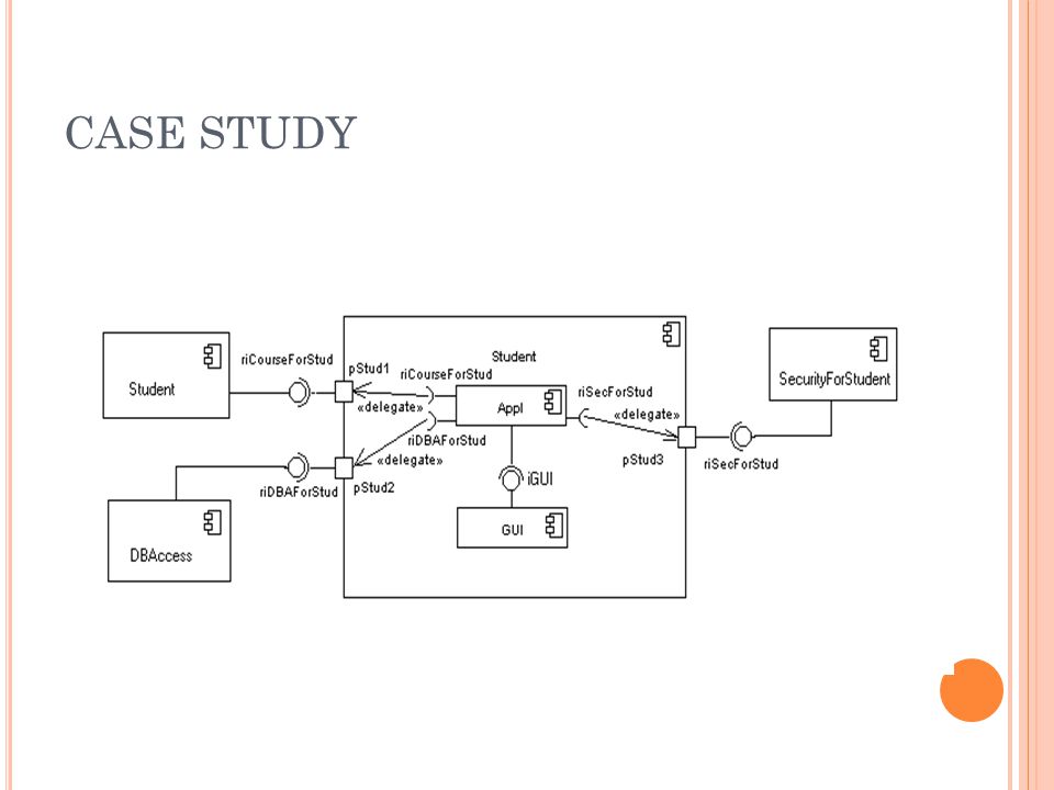
CASE STUDY Pengembangan aplikasi jajak pendapat siswa tentang program Siswa dapat Membaca Menyisipkan Mengupdate Membuat data permanen mengenai program di jadwal Seorang profesor hanya bisa melihat elaborasi statistik data Aplikasi mahasiswa harus diinstal di klien pc (sw1, sw2) Manajer aplikasi harus diinstal di klien pc (di kantor manajer) Ada satu atau lebih server dengan DataBase dan komponen untuk manajemen program
 Manajer aplikasi harus diinstal di klien pc (di kantor manajer) Ada satu atau lebih server dengan DataBase dan komponen untuk manajemen program")
8
COMPONENT NOTATION A component is shown as a rectangle with A component is shown as a rectangle with A keyword > A keyword > Optionally, in the right hand corner a component icon can be displayed Optionally, in the right hand corner a component icon can be displayed A component icon is a rectangle with two smaller rectangles jutting out from the left-hand side A component icon is a rectangle with two smaller rectangles jutting out from the left-hand side This symbol is a visual stereotype This symbol is a visual stereotype The component name The component name Components can be labelled with a stereotype Components can be labelled with a stereotype there are a number of standard stereotypes ex: >, >

9
C OMPONENT ELEMENTS A component can have Interfaces Sebuah interface merupakan deklarasi dari satu set operasi dan obligations Usage dependencies usage dependency adalah hubungan yang salah satu unsur memerlukan unsur lain untuk implementasi penuh Ports Port merupakan titik interaksi antara komponen serta lingkungan Connectors Connect two components Connect the external contract of a component to the internal structure

10
INTERFACE provided dan required Komponen mendefinisikan perilaku dalam hal interface provided dan required An interface An interface Merupakan definisi dari kumpulan satu atau lebih operasi Hanya menyediakan operasi tetapi tidak implementasinya Implementasi biasanya disediakan oleh kelas / komponen Dalam sistem yang kompleks, Implementasi disediakan oleh sekelompok kelas daripada satu kelas

11
INTERFACE May be shown using a rectangle symbol with a keyword > preceding the name For displaying the full signature, the interface rectangle can be expanded to show details Can be Can be Provided Provided Required Required

12
INTERFACE A provided interface Characterize services that the component offers to its environment Is modeled using a ball, labelled with the name, attached by a solid line to the component A required interface A required interface Characterize services that the component expects from its environment Characterize services that the component expects from its environment Is modeled using a socket, labelled with the name, attached by a solid line to the component Is modeled using a socket, labelled with the name, attached by a solid line to the component In UML 1.x were modeled using a dashed arrow In UML 1.x were modeled using a dashed arrow

13
INTERFACE 2 komponen / kelas dapat memberikan atau membutuhkan interface yang sama sehingga notasi dapat dikombinasikan. Notasi Ball-and-socket menggambarkan interaksi diantara 2 komponen yang saling membutuhkan Notasi Ball-and-socket menggambarkan interaksi diantara 2 komponen yang saling membutuhkan If an interface is shown using the rectangle symbol, we can use an alternative notation, using dependency arrows If an interface is shown using the rectangle symbol, we can use an alternative notation, using dependency arrows

14
INTERFACE A component Specifies a CONTRACT of the services that it provides to its clients and that it requires from others components in terms of its provided and required interfaces Can be replaced The system can be extended Pada kontek sistem dimana terdapat multipel komponen yang membutuhkan atau memberikan interface tertentu, notasi abstrak dapat digunakan untuk mengkombinasikan. Pada kontek sistem dimana terdapat multipel komponen yang membutuhkan atau memberikan interface tertentu, notasi abstrak dapat digunakan untuk mengkombinasikan.

15
DEPENDENCIES Usage Dependency usage dependency merupakan relasi dimana satu elemen membutuhkan elemen lain untuk implementasi penuh Merupakan dependensi dimana client membutuhkan kehadiran suplier. Digambarkan sebagai panah putus dengan > keyword The arrowhead point from the dependent component to the one of which it is dependent Components can be connected by usage dependencies Components can be connected by usage dependencies

16
PORT Is shown as a small square symbol Is shown as a small square symbol Ports can be named, and the name is placed near the square symbol Ports can be named, and the name is placed near the square symbol Is associated with the interfaces that specify the nature of the interactions that may occur over a port Is associated with the interfaces that specify the nature of the interactions that may occur over a port Menspesifikasikan titik interaksi Menspesifikasikan titik interaksi Between that component and its environment Between that component and its environment Between that component and its internal parts Between that component and its internal parts

17
PORT Ports can support unidirectional communication or bi-directional communication If there are multiple interfaces associated with a port, these interfaces may be listed with the interface icon, separated by a commas If there are multiple interfaces associated with a port, these interfaces may be listed with the interface icon, separated by a commas

18
PORT Semua interaksi komponen dengan lingkungan dilakukan melalui port. Internal tertutup rapat dari lingkungan Ports are not defined in UML 1.x

19
EXTERNAL VIEW An external view (or black box view) memperlihatkan properti dan operasi yang publik The interface can be listed in the compartment of a component box The interface can be listed in the compartment of a component box Komponen memiliki external view dan internal view Komponen memiliki external view dan internal view
 memperlihatkan properti dan operasi yang publik The interface can be listed in the compartment of a component box The interface can be listed in the compartment of a component box Komponen memiliki external view dan internal view Komponen memiliki external view dan internal view")
20
INTERNAL VIEW An internal, atau white box view komponen merupakan kelas/komponen yang terealisasikan dalam komponen Realization is merupakan realisasi diantara 2 set model elemen Realization is merupakan realisasi diantara 2 set model elemen Satu merepresentasikan spesifikasi Satu merepresentasikan spesifikasi Lainnya merepresentasikan implementasi Lainnya merepresentasikan implementasi

21
INTERNAL VIEW The internal class that realize the behavior of a component may be displayed in an additional compartment Compartments can also be used to display parts, connectors or implementation artifacts Compartments can also be used to display parts, connectors or implementation artifacts An artifact is the specification of a phisycal piece of information An artifact is the specification of a phisycal piece of information

22
INTERNAL VIEW Components can be built recursively Components can be built recursively

23
ASSEMBLY Dua macam konektor Delegation Assembly ASSEMBLY CONNECTOR Konektor diantara 2 komponen mendefinisikan bahwa satu komponen memberikan layanan yang dibutuhkan oleh komponen lain. Harus didefinisikan dari required interface ke provided interface An assembly connector is notated by a “ball-and- socket” connection

24
DELEGATION DELEGATION CONNECTOR DELEGATION CONNECTOR Links the external contract of a component to the internal realization Links the external contract of a component to the internal realization Represents the forwarding of signals Represents the forwarding of signals He must only be defined between used interfaces or ports of the same kind He must only be defined between used interfaces or ports of the same kind

25
DELEGATION The target interface must support a signature compatible with a subset of operations of the source interface A port may delegate to a set of ports on subordinate components The union of the target interfaces must be signature compatible with the source interface Semantics: Is a declaration that behaviour that is available on a component instance is not realized by that component itself, but by another instance that has compatible capabilities Is used to model the hierarchical decomposition Message and signal flow will occur between the connected ports

26
CASE STUDY

28
DEPLOYMENT DIAGRAMS Deployment diagrams Show the physical relationship between hardware and software in a system Hardware elements: Computers (clients, servers) Embedded processors Devices (sensors, peripherals) Are used to show the nodes where software components reside in the run-time system There is a strong link between components diagrams and deployment diagrams There is a strong link between components diagrams and deployment diagrams
 Embedded processors Devices (sensors, peripherals) Are used to show the nodes where software components reside in the run-time system There is a strong link between components diagrams and deployment diagrams There is a strong link between components diagrams and deployment diagrams")
29
DEPLOYMENT DIAGRAMS Deployment diagram Deployment diagram Contains nodes and connections Contains nodes and connections A node usually represent a piece of hardware in the system A node usually represent a piece of hardware in the system A connection depicts the communication path used by the hardware to communicate A connection depicts the communication path used by the hardware to communicate Usually indicates the method such as TCP/IP Usually indicates the method such as TCP/IP

30
DEPLOYMENT DIAGRAMS An artifact An artifact Is the specification of a phisycal piece of information Is the specification of a phisycal piece of information Ex: source files, binary executable files, table in a database system,…. Ex: source files, binary executable files, table in a database system,…. An artifact defined by the user represents a concrete element in the physical world An artifact defined by the user represents a concrete element in the physical world Deployment diagrams contain artifact Deployment diagrams contain artifact

31
DEPLOYMENT DIAGRAMS An artifact manifest one or more model elements A > is the concrete physical of one or more model elements by an artifact This model element often is a component A manifestation is notated as a dashed line with an open arrow-head labeled with the keyword > A manifestation is notated as a dashed line with an open arrow-head labeled with the keyword >

32
DEPLOYMENT DIAGRAMS

33
REFERENCIES UML 2.0 Superstructure Specification August 2, 2003 UML 2 Superstructure Final Adopted Specification www.omg.org/cgi-bin/doc?ptc/2003-08-02 The Diagrams of UML 2.0 by Scott W. Ambler, 2003-2004 www.agilemodeling.com/essays/umlDiagrams.htm UML overview By Mandar Chitnis, Pravin Tiwari, & Lakshmi Ananthamurthy http://www.developer.com/design/article.php/1553851

Presentasi serupa


>")


